MAN0984_Iss 4_01/19 Touchpoint Plus
Pt. No. 3011M5001 87 Technical Handbook
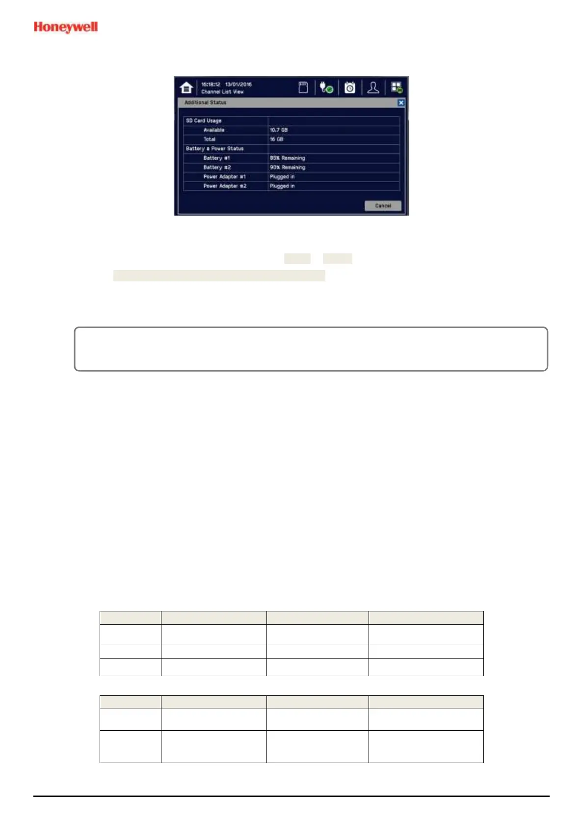
8) Check the SD Card status by touching on either the SD Card or Power Icons:
9) If the SD Card is new, full or has a fault, log in as Admin or Service.
10) Touch Menu>Maintenance>SD Card>Format>Yes
11) Close the window and log out when finished.
12) Re-check the SD Card status by touching on either the SD Card or Power Icons again.
7.6
Normal Operation (Safety
Functions)
During normal operation:
• The Touchpoint Plus system will collect sensor data every 1 second.
• Input channel gas calculation is compared to alarm setpoints every 500 ms.
• Input channel gas calculation is checked for over/under range value every 500 ms.
• Cycle time of the Main Module is 1 second until data are sent to the output modules (UI, relay, mA)
• Any failure of the safety function i.e. due to major fault or power loss will activate the System Failure relay. System
Failure relays are updated at the end of each 1 second cycle.
• The Cause and Effect matrix will be evaluated every 1 second, and commands sent accordingly to the appropriate
output channels.
• Any change in status of an I/O channel will be reported to the User Interface and logged in the event history.
• Events (Alarms, Faults, Inhibits, etc.) will be reported to the User Interface and logged in the event history.
• Be careful with the mA output and relay setting as user can configure the setting of mA output and relay
operation. Below table shows the recommendation of mA output and relay setting for safety function of
Touchpoint Plus. One of either RLY1 or RLY2 in main board shall be configured to system inhibit relay

 Loading...


