Electrical Power Connection and Interfacing
MAN0984_Iss 4_01/19 Touchpoint Plus
Pt. No. 3011M5001 37 Technical Handbook
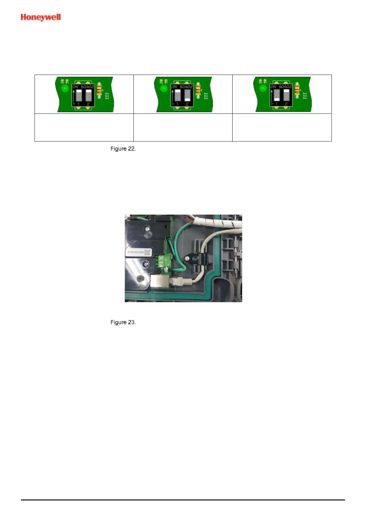
5.2.7 TPPL DIP Switches
TPPL Backplanes have a DIP switch that controls the interaction between the basic (Controller) and the expansion
(slave) unit backplanes. Set them as shown below.
Basic Unit Alone
2, 4, or 8 Channels
Both On
Basic Unit with Expansion Unit
10, 12, or 16 Channel Expansion
1 On, 2 Off
Expansion Unit
10, 12, or 16 Channel Expansion
Always 1 Off, 2 On
Backplane DIP Switch Settings
5.2.8 Ethernet Connection (Option)
Ethernet cable must be CAT5e or CAT6 Ethernet cable terminated to TIA/EIA-568B standard. The cable should have
shielded RJ45 plugs with the shield of the cable bonded to the metal body (shield) of the connector plug. The cable
length should not exceed 100 m. The Ethernet cable should be fitted through a gland to preserve the IP rating.
Connect an Ethernet Network (Web Interface) cable by routing it through a suitable gland and cable clamps before
plugging it into the lower right of the Motherboard as shown below:
Ethernet Cable Fitting

 Loading...


