4188-856_issue 7_07/15_Generic Vigilon (Compact + VA) Comms. 29
Vigilon 4/6 loops & Compact (VA) panels & network nodes
Vigilon 4/6 loop Panels
Pre power-up checks
¨
The mains cable is the only external cable that is required to be connected at this initial stage.
Other external circuit cables are left disconnected, but are connected and tested later, they
include:
•
all loop circuits
•
clean contacts
•
auxiliary circuits
•
master alarm circuits, has the end-of-line resistors (22K Ohm) fitted to the terminals on the
terminal card to inhibit a master alarm circuit fault indication.
•
and RS232/RS485
"
A networked system is commissioned after all the individual standalone systems are fully
commissioned.
¨
Ensure all cards are securely fitted into their appropriate slots on the backplane.
¨
Ensure all ribbon cables are securely fitted into their respective sockets.
Mains supply wiring
&
1. The fire alarm system products are NOT designed to be powered from
IT Power systems.
2. All mains powered equipment must be earthed.
Ensure the mains supply cable enters the equipment via a dedicated cable entry point, which is located
adjacent to the mains terminal block and is also segregated from other loop wiring.
¨
Mains supply to any fire alarm control and indicating equipment must be via an unswitched 5A
fused spur unit. A disconnect device must be provided to disconnect both poles and must have a
minimum gap of 3mm. The 'disconnect device' should be available as part of the building
installation and must be easily accessible after installation is complete.
¨
The fused spur isolator unit cover should be marked:
FIRE ALARM - DO NOT SWITCH OFF
¨
The Mains power is switched on after battery is installed and connected.
&
Hazardous voltage remains after operation of a protection
fuse. Take appropriate action to guard against the risk of equipment
having exposed live mains supply.
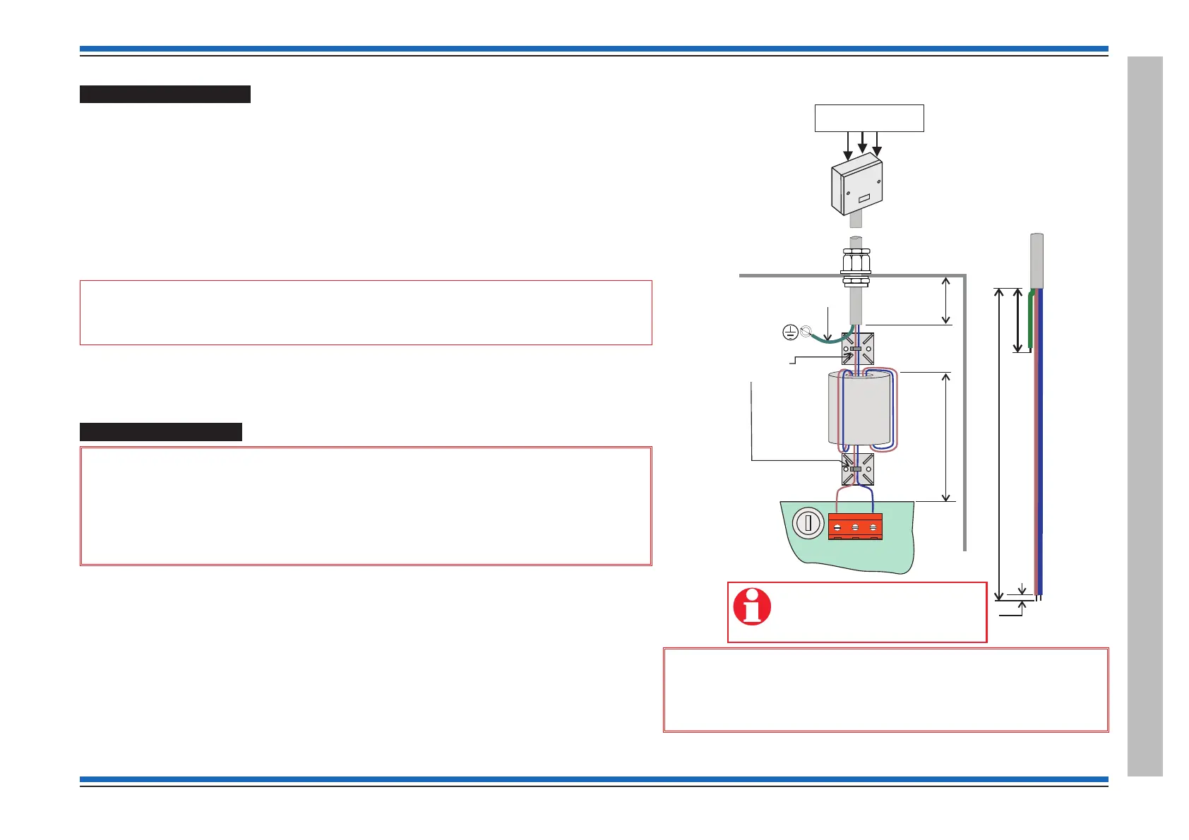
P2
L
N
PSU PCB
The mains cable must be stripped
back to the length shown to allow
live and neutral wires to be wound
through the ferrite core.
Dedicated mains supply
from consumer unit
5A Unswitched
fused spur unit
max. 230V ac
Panel
must be sleeved
Use cable ties
(supplied)
ferrite
core
(supplied)
45mm
35mm
Gland
270mm
50mm
5mm
mains
cable

 Loading...