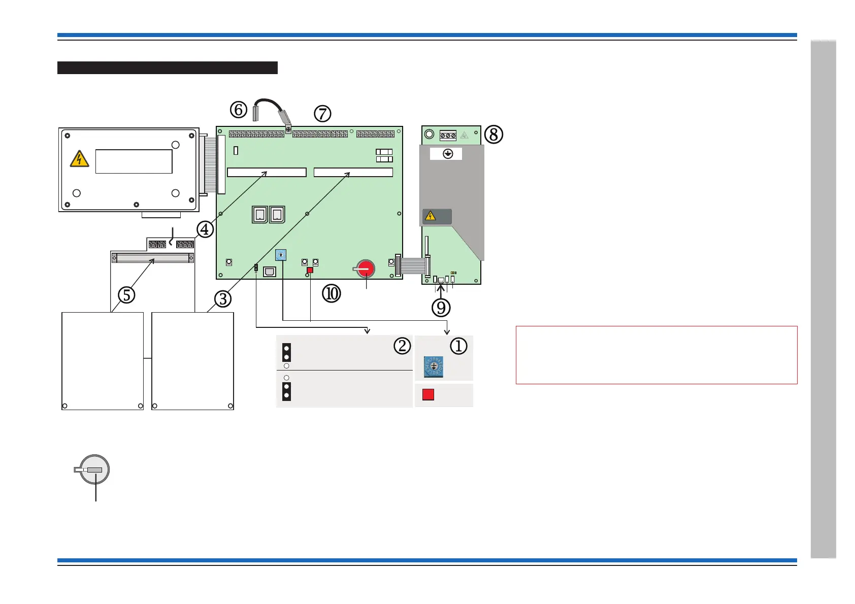
Cards and internal cables of the panel
Battery
The lithium battery s is disconnected on leaving the factory by means of an insulation disk over
the top connector. The insulation disk must be removed before powering up the system.
Set the Rotary switch SW2
This switch is set to the required position for the panel build on leaving the
factory. Before installing the Loop cards and Network card onto the Master
control board MCB ensure the switch
j SW2 is set to a required setting if
the panel is to be installed in an existing system, see table on the next page.
NVM hardware link P13
The NVM can be enabled or disabled by setting the hardware link k on the
MCB. If the NVM protect is hardware disabled then it is also possible to
software enable or disable the NVM using the [Protect] option under the
[Setup] menu at the panel.
Unprotect: Normally during commissioning the NVM is disabled
(unprotected) and writing to NVM is allowed.
Protect: Once the configuration is backed up to the NVM the hardware link
must be in the enabled position to disallow writing to the NVM.
Installing the Cards
The MCB can accommodate two Loop Cards. One Loop card l can be
fitted into the slot labelled CARD1 and the other Loop card
n into the slot
labelled CARD2.
"
A networkable system has a Network Card m fitted into
the slot CARD 2 on the MCB and additionally the Network Card can
accommodate the second Loop card.
Earth Link
The earth link lead o is supplied with the Network Card. This link lead
must be fitted to the spade connector on the top edge of MCB with the other
end to the spade connector on the Network Card.
Terminals
The terminal blocks p on the top edge of the MCB are used for wiring
external circuits. The terminal block
q on the top edge of the PSU is used
for wiring the mains supply to the panel. The connector
r located on the
bottom edge of the PSU board is used to connect the battery supply.
4188-856_issue 7_07/15_Generic Vigilon (Compact + VA) Comms. 35
Vigilon 4/6 loops & Compact (VA) panels & network nodes
Vigilon Compact Panel
WARNING
REMOVAL OF COVER
EXPOSES HIGH VOLTAGE
KEYBOARD INDICATORS AND DISPLAY
L2-
0V
L2+
L1-
0V
PB1A PB1B
P2
PP2
Network Card
Loop Card 2
P13
P13
SW1
RESET
SW2
MODE
NVM Protect - [Disabled]
NVM Protect - [Enabled]
BATT3
PB15 PB6
PB9
P2 CARD 1
IC3
KEYBOARD
IC16
POWER
SUPPLY
P12
MA2 - FS2 250mA
MA1 - FS1 250mA
P1 CARD 2
P16
P13
SW1
RESET
24V B A
0V
TX1 RX1
0V
PB8
MA1+
MA1- MA2+
MA2-
0V
MIPNC C
NO
FIRMWARE
BACKUP
PB10
PB7
L1 0V L2 0V
24V
FS3 200mA
TX2 RX2
PB14
L1 0V L2 0V
NC
C
NO
NC
C
NO
NC
C
NO
PB11
Master Control
Board (MCB)
Power Supply Unit
(PSU)
P2
P1
N
E
L
FS3 3.15A(T)
Mains fuse
P3
DANGER
FS6
1A TE5
43V
FS4 - 1A TE524V
P7
BAT1
FS1 - 3.15A TE5Bat 1
Remove
insulation disk
L
N
Warning
Removal of
cover exposes
live parts
DANGER
SW2
MODE
Loop Card 1
L1+
 Loading...