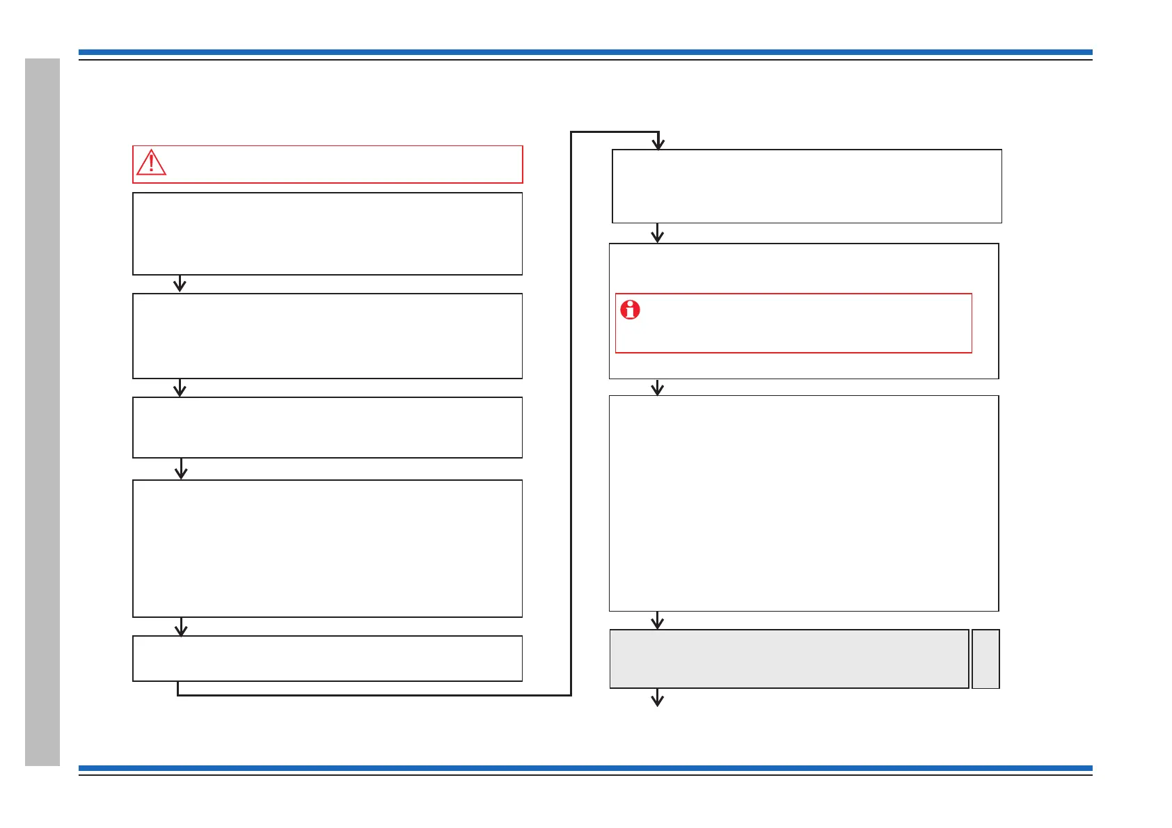
Before powering up the Panel
Open the outer cover and inner cover of the panel and:
– Check all the internal cables within the enclosure are securely fitted
– Ensure no external circuits are connected at this stage, except for
the mains supply which must be connected but not switched ON
–
– Fit the loop card(s) into the required location(s)
Fit the resistors to the master alarm circuits.
– Connect the external printer to the RS232 port, if required.
– Ensure the input - output lines of interface units on the loop are not
connected.
end of line
Inform responsible person(s)
Inform responsible person(s) that the fire alarm system is being
commissioned and occupants in the protected premises will hear
test alarms.
Ensure occupants are made aware of alternative site procedures
should there be a fire event while the system is commissioned.
Pre visit checks
Ensure you have:
shows installed system equipment
Installer will be present to rectify wiring faults
Tools and spare parts are available.
–
–
–
–
As-fitted-drawings that
Access will be available to protected areas having system equipment
Always power-down the panel when
.
working on the system,
for example when wiring or replacing parts
Survey the installation
Refer to the most recent and ensure that all the fire
system equipment has been installed in accordance with the
installation instructions, respective standards and project specification.
as-fitted-drawings
Power up
– Fit the batteries inside the panel enclosure and connect the battery
leads and then switch ON the mains supply.
Initial tests and set ups
– Carry out a display test and ensure DISPLAY and LEDs are working
– Set the system clock time and date
Configure the RS232 printer port, if an external printer is installed.
– Setup Access levels PIN codes, if required
–
Loop Devices
Configure the links on all LV 4-channel interface units connected to
the loop. Ensure links are set for either Input or Output application.
–
– Power up the mains powered interface unit on the loop.
Ensure all interface Input/Output external wiring remains
disconnected at this stage, unless otherwise instructed. This
action will prevent inadvertent operation of output/plant while
the system is being commissioned.
Loop device address allocation
– Connect only End 1 of a loop circuit and power-up the loop
– Allow address allocation to finish. Any fault(s) on the loop during
allocation must be rectified. Power-down the loop when correcting
loop wiring faults and the power-up to continue address allocation
– Connect only End 2 of the loop circuit and power cycle the loop and
ensure address allocation is complete from End 2.
– Connect both End 1 and End 2 of the loop and check the loop
allocation is complete with both ends of the loop connected.
– ‘Starting Loop n’ displayed after successful allocation of addresses.
– Check all the devices on the loop circuit are installed in their correct
location using the ‘ ’ function at the panel and by referring
to the ‘ ’
– Check to ensure correct devices are installed by viewing the
‘Device status’
– Repeat the allocation process on other loop circuits.
Find Device
as fitted wiring drawings
Continue on next page
Pre-allocate the wireless devices
– If the system has wireless devices then pre-allocate the
wireless devices and bind them to the respective LRT.
Then allocate loop again to allow panel to see the devices.
Radio
Devices
 Loading...