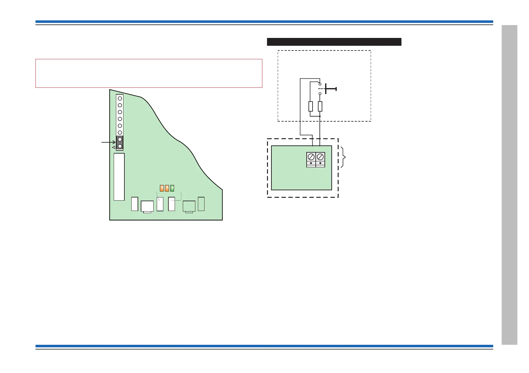
PSU EEPROM link
Ensure a shorting link is fitted to the programming header P1 located on the PSU. The link must be
fitted such that it shorts pins 1 and 2. This enables the EEPROM hardware write protect.
"
The link is supplied fitted on the PSU board manufactured after September 2007.
How to configure the monitored input
The monitored input at the fire panel is activated by an external switch installed a maximum of
100m cable distance away from the fire panel. The input is monitored for both short and open
circuit faults. When the input is active it triggers the command build number 250 of the fire panel.
Example
The following example shows how to configure the monitored input at the panel to provide an
output sound signal 1 alarm in sector 2 of loop 1 as a reversible action. This means on operating or
"closing" the monitored input the panel will start alarms in sector 1 and on releasing or "opening"
the monitored input the panel will stop all the alarms from sounding.
# - will appear if a PIN is setup.
The following procedures assume a password entry is not required.
Press Menu On/Off button and select [SetUp] -> [Usercode]#, momentarily press <etc> to select
[SetUp] -> [Build] and type in the command build number 250, select [Action] -> [UserCode],
momentarily press <etc> to select [Sector], type in 2 for sector 2 and select [Loop] and type in 1
for Loop 1 -> [Action] -> [Signal 1] -> [Enter] -> [reversb] -> [Enter].
4188-856_issue 7_07/15_Generic Vigilon (Compact + VA) Comms. 41
Vigilon 4/6 loops & Compact (VA) panels & network nodes
Vigilon Compact Panel
P8
0V
MIP
PANEL
2 - 10K Ohms -
resistors must be
fitted as shown.
MASTER CONTROL
BOARD
Normally open contacts
An active input will trigger
the command build No 250
The command build action
is configured during commissioning.
Monitored Input
These contacts can be a push button
switch, fire/fault relay contacts from
another panel or contacts from a timer.
P3
43V
FS6
1A
24V FS4 - 1A
P7
BAT1
Bat1 - FS1 - 3.15A
+
-
Y1 Y2 G1
PSU BOARD
(part view)
P1
Ensure a link
is fitted accross
pins 1-2

 Loading...