Loop circuit tests
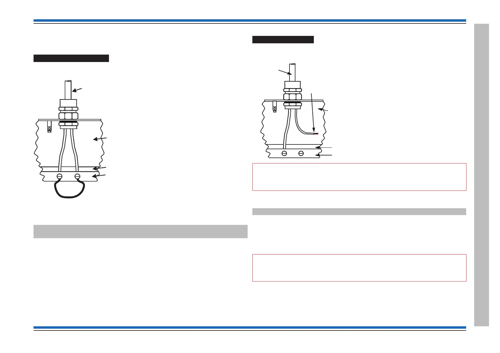
Loop short circuit test
A loop short circuit isolation test should be carried out at this stage. It is recommended that the
sounders are switched On before conducting this test.
End 1 Short test
¨
Create a short circuit by wiring a link across the loop terminals at End-1. There
should be no loss of any part of the system. The display should read:
Wiring changed - short at card x number y loop z
Wiring changed - loop split
¨
After rectification (removal of the short circuit) you will need to [Repair] the loop
circuit.
End 2 and Mid circuit Short test
¨
A short circuit test should then be repeated at End-2 and again at mid point of the
loop.
¨
After each test carry out rectification (remove the short circuit) you will then need to
[Repair] the loop circuit, see page 62 .
Ground break test
A ground break test should be carried out at this stage:
¨
Disconnect the 0V line from End-1 of a loop circuit.
"
A single 0V line break should not cause the loss of any part of the system.
End 1 cable break test
¨
The cable break may have to be sustained for up to a minute. The display should read:
Wiring changed - ground break at card x number y on loop z
¨
To clear the fault, the 0V line should be reconnected and then the loop should be
repaired using the [Repair] function at the panel.
End 2 loop break test
¨
The ground break test should be repeated at the other end of the loop circuit, End-2
and again at Mid point of the loop.
"
The exact location of a ground break is not indicated at the panel, however the
loop will run as normal.
¨
To clear the fault, the 0V line should be reconnected and then the loop should be
repaired using the [Repair] function at the panel, see page 62.
4188-856_issue 7_07/15_Generic Vigilon (Compact + VA) Comms. 63
Vigilon 4/6 loops & Compact (VA) panels & network nodes
Loop circuit tests
L1 0V
LOOP CABLE
BOARD
TERMINALS
BOARD
PANEL
enclosure
REMOVE THE 0V
LINE TO
INTRODUCE A
GROUND BREAK
L
1
0V
TERMINALS
BOARD
PANEL
enclosure
LOOP CABLE
SHORTING LINK
 Loading...