36
NTP broadcast mode configuration example
Network requirements
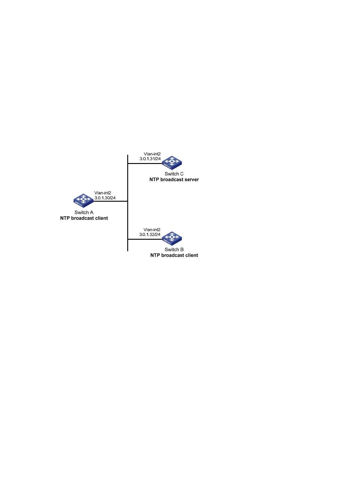
As shown in Figure 13, Switch C functions as the NTP server for multiple devices on a network segment
and synchronizes the time among multiple devices.
• Switch C's local clock is to be used as a reference source, with the stratum level 2.
• Switch C operates in broadcast server mode and sends out broadcast messages from
VLAN-interface 2.
• Switch A and Switch B operate in broadcast client mode, and listen to broadcast messages through
VLAN-interface 2.
Figure 13 Network diagram
Configuration procedure
1. Set the IP address for each interface as shown in Figure 13. (Details not shown.)
2. Configure Switch C:
# Enable the NTP service.
<SwitchC> system-view
[SwitchC] ntp-service enable
# Specify the local clock as the reference source, with the stratum level 2.
[SwitchC] ntp-service refclock-master 2
# Configure Switch C to operate in broadcast server mode and send broadcast messages through
VLAN-interface 2.
[SwitchC] interface vlan-interface 2
[SwitchC-Vlan-interface2] ntp-service broadcast-server
3. Configure Switch A:
# Enable the NTP service.
<SwitchA> system-view
[SwitchA] ntp-service enable
# Configure Switch A to operate in broadcast client mode and receive broadcast messages on
VLAN-interface 2.
 Loading...