To replace the component, reverse the removal procedure.
CAUTION: Carefully align the backplane center through-holes with the chassis mounting posts
or you might damage components on the backplane.
Removing and replacing the PCI riser cage
To remove the component, see “Removing the PCI riser cage” (page 43).
To replace the component, reverse the removal procedure.
Removing and replacing expansion slot covers
To remove the component see “Removing expansion slot covers” (page 44).
To replace the component, reverse the removal procedure.
Removing and replacing expansion boards
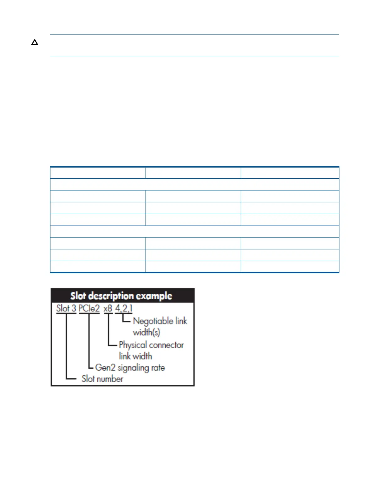
Table 39 PCI slot descriptions
2–slot PCIe riser3–slot PCIe riser
Primary riser connector
PCIe2 x16 (8, 4, 2, 1)PCIe2 x16 (8, 4, 2, 1)1 — Full length, full height
PCIe2 x16 (8, 4, 2, 1)PCIe2 x8 (4, 2, 1)2 — Half length, full height
—PCIe2 x8 (4, 2, 1)3 — Half length, full height
Secondary riser connector
PCIe2 x16 (8, 4, 2, 1)PCIe2 x16 (8, 4, 2, 1)4 — Full length, full height
PCIe2 x16 (8, 4, 2, 1)PCIe2 x8 (4, 2, 1)5 — Low profile
—PCIe2 x8 (4, 2, 1)6 — Low profile
The server supports up to two PCIe riser boards. Each PCIe riser board holds up to three PCIe cards
each. The standard riser board configuration contains one riser board with one full-length, full-height
PCIe x8 slot, and two half-length, full-height PCIe x4 slots. The second board contains one full-length,
full-height PCIe x8 slot, and two half-length, half-height PCIe x4 slots.
The optional riser board configuration contains one riser board with one full-length, full-height PCIe
x8 slot, and two half-length, full-height PCIe x4 slots. The second board contains one full-length,
full-height PCIe x16 slot.
104 Removal and replacement procedures
 Loading...