System board
Removing the system board
1. Disconnect power from the system ( Pre-disassembly procedures on page 53), and remove the
access panel (
Access panel on page 58). Place the workstation on its side with the system board
facing up. Remove all expansion boards, graphics cards (
Removing PCI or PCI Express cards
on page 72), and the CPU heatsink (Processor heatsink on page 86). If an airflow duct is installed,
remove the system/memory fan assembly (
Power supply on page 63).
2. Disconnect all cables from the system board.
CAUTION Be sure you can differentiate which power cable was disconnected from the
PCI Express x16 graphics card and which power cable was disconnected from the system
board. These two cables look similar. The PCI Express power cable has a black connector
and the power cable has a white connector. When power is present, NEVER connect the
PCI Express power cable to the system board. If you do so, the system board can be
damaged and your warranty voided. To see a picture of the PCI Express cable and where
it must be connected, see
PCI or PCI Express installation on page 73.
NOTE Make note of the cable connections before disconnecting them from the system
board. See
Power connections to drives on page 76for more information.
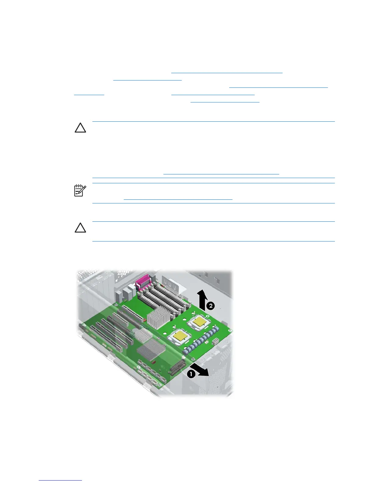
3. Slide the system board forward (1) to disengage the metal mounting standoffs from the chassis.
CAUTION Do not attempt to remove the eight system board mounting screws. These
screws are permanently secured and are not removable.
4. Lift the system board out (2) of the chassis, being careful not to damage the cables and rear panel
connectors. You can lift the board by the rear audio connector and the 2 x 4 power connector.
Figure 4-50 Removing the system board
92 Chapter 4 Removal and replacement procedures ENWW
 Loading...