PCI bus layout and device list
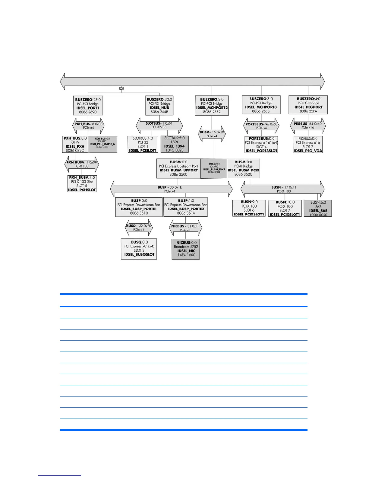
The following illustration shows the HP xw8400 Workstation PCI bus layout. It is followed by a PCI device
list description.
Figure J-1 PCI bus layout
Table J-1 PCI device list
Device Bus# Dev# Fn#
Intel® 5000X Chipset Memory Controller Hub (BUS0) 0 0 0
Intel PCI Express x4 MCH Port 2 (MCH to ICH Bridge) 0 2 0
Intel PCI Express x4 MCH Port 3 (Bridge for PCI-E x16 — Slot 4) 0 3 0
Intel PCI Express x16 MCH Port 4 (Bridge for PCI-E x16 — Slot 2) 0 4 0
Port 5, Slave Port of Port 4 00 5 00
Port 6, Slave Port of Port 4 00 6 00
Port 7, Slave Port of Port 4 00 7 00
Intel 5000 Series Chipset Error Reporting Registers 00 16 00
Intel 5000 Series Chipset Error Reporting Registers 00 16 01
Intel 5000 Series Chipset Error Reporting Registers 00 16 02
Intel 5000 Series Chipset Reserved Registers 00 17 00
200 Appendix J Appendix J —PCI bus layout ENWW
 Loading...