5 | Product Overview INFICON
28 / 319 074-594-P1H Micro GC Fusion Operating Man-
ual
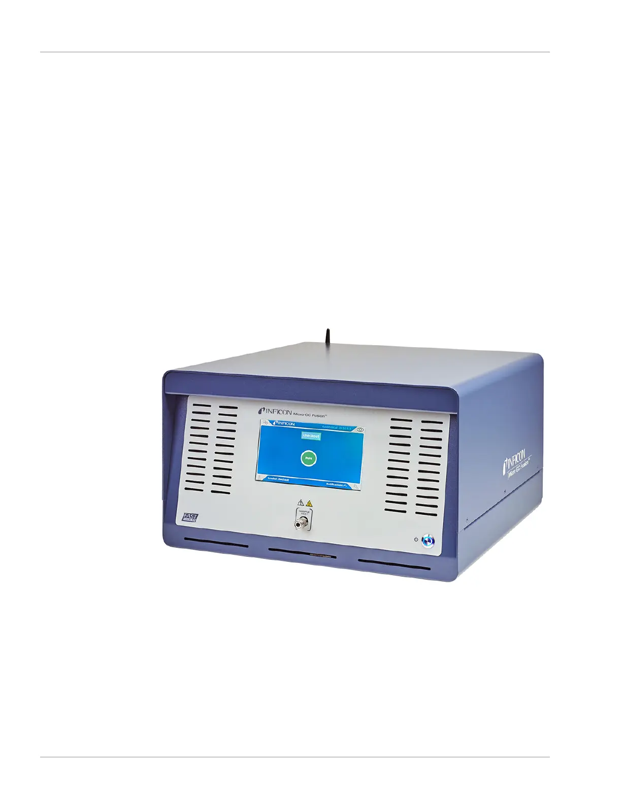
5.2 4-Module Chassis
The 4-module Micro GC Fusion chassis houses up to four analytical GC modules,
electrical components and internal plumbing. The front panel display provides access
to basic operating interfaces and controls.
• Heated sample inlet
– The inlet is a 1/16 in. Swagelok
®
male connector. A 1/8 in. quick connect is
provided if the optional integrated sample conditioner is installed.
• Front panel display
– See Front Panel Operation [
}149] for details about using the front panel dis-
play to access routine operating controls.
• On/Standby button
– Use the illuminated On/Standby button to power on or place the instrument in
standby mode.
Electrical and gas connections are located on the Micro GC Fusion back panel.

 Loading...