INFICON Installation | 6
074-594-P1H Micro GC Fusion Operating Manual 95 / 319
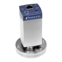
6.12 The AUX I/O Connector
For some applications, an external triggering device may be required for sampling.
This can be accomplished by connecting an external triggering device to the Micro GC
Fusion AUX I/O port via a Remote Start Cable (PN G2801-60618). This cable has a
15 pin connector at one end. The other end can be fitted with a desired connector
type.
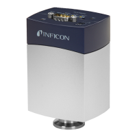
2-Module chassis:
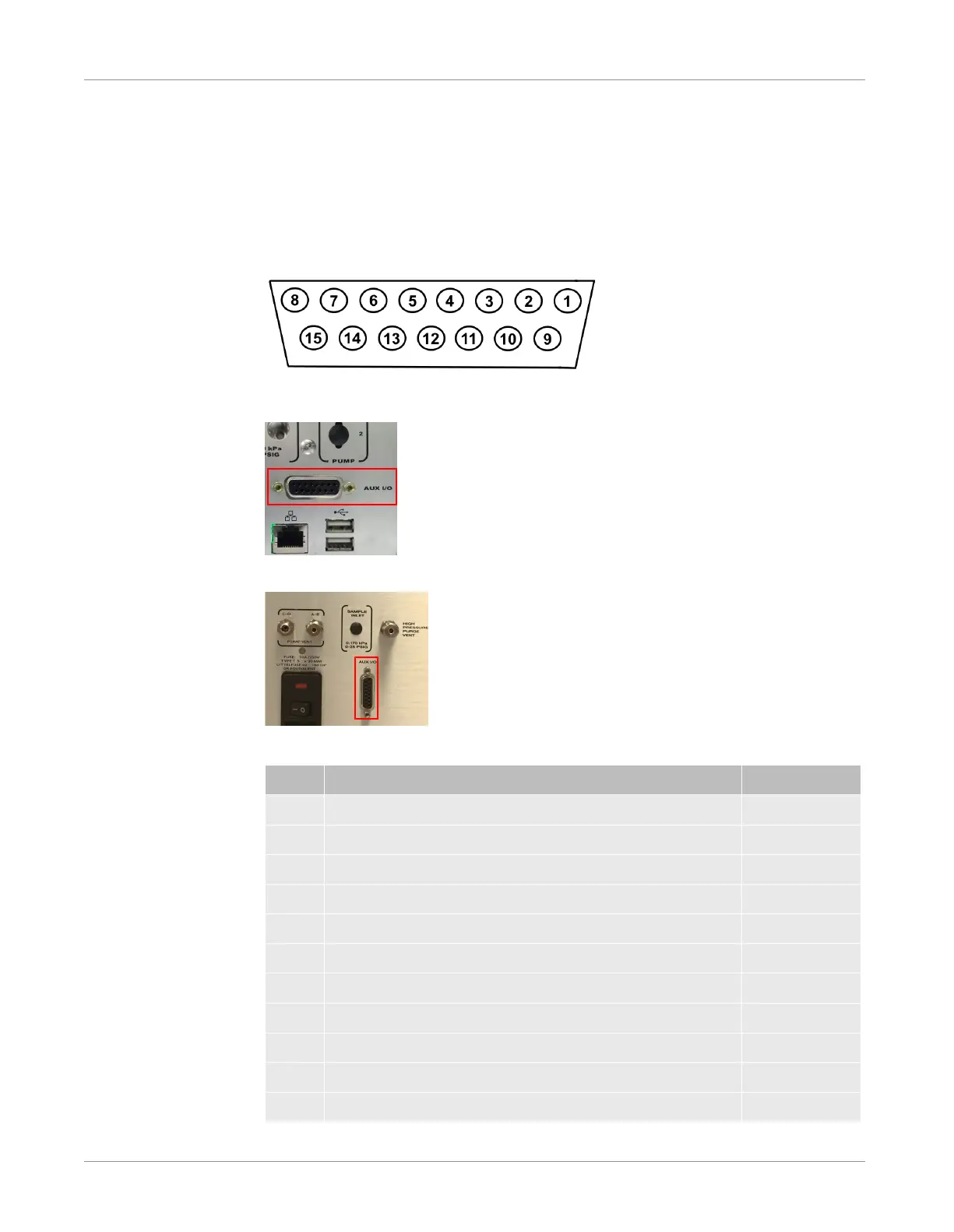
4-Module chassis:
The AUX I/O connector pin outputs are listed in the table below.
Pin Function Color
1 Provides 5 mA remote input Black
2 REMOTE_START input White
3 REMOTE_START input Red
4 Variable GND Green
5 Provides "5V pull up" for logic command Orange
6 Provides "5V pull up" for logic command Blue
7 Contact closure output FAULT_OUT* White/black
8 Contact closure output READY_OUT Red/black
9 Provides 5 mA for remote input Green/black
10 REMOTE_CANCEL input Orange/black
11 REMOTE_CANCEL input Blue/black

 Loading...