INFICON Installation | 6
074-594-P1H Micro GC Fusion Operating Manual 71 / 319
6.5 Installing the Rack Mount Kit
6.5.1 Rack Mount Kit (PN 952-4100-G1) Parts
PN Description Quantity
952-4005-P2 Bracket-rack mount right (with handle) 1
952-4006-P2 Bracket-rack mount left (with handle) 1
070-2026* Handle 6.375 LG 2-leg 10-32 THD SS RoHS 2
070-2028 Washer countersink #10 hole 0.593 OD SS 8
070-2027 Nut retainer G-type 10-32 THD Steel/ZN RoHS 8
090-062 Screw, 10-32 x 0.375 lg phil flat head SS 6
090-077 Screw, 10-32 x 0.750 lg phil oval head SS 8
074-683-P1 Micro GC Fusion rack mount IS 1
*PN 070-2026 is preassembled on PN 952-4005-P2 and 952-4006-P2 at the factory.
6.5.2 Required Tools
• Phillips-head screw driver
• 3 mm hex driver
6.5.3 Rack Mount Kit Installation
The following procedure indicates the necessary materials and proper procedure
when installed the 4-module Micro GC Fusion into a rack.
1
Ensure the instrument is turned off and all connections are removed (including
the power supply, Ethernet cable and carrier gas lines).
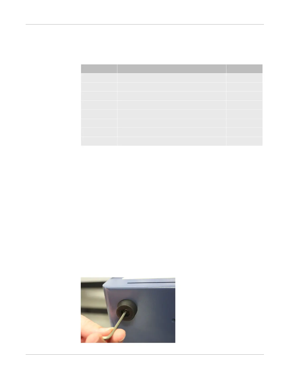
2
Remove the rubber feet from the bottom of Micro GC Fusion by removing the
hex screw located at the center of the foot. Properly store the rubber feet and
screws for future bench top installation.

 Loading...