Eclipse Additional Information Page 45
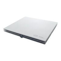
Overview of Filtering and Recording
In general the advice is to follow the default parameter of the factory protocols. On some occasions there
might be an electrical noise source within the testing environment which 'forces' you to apply some stricter
filtering to get rid of the problems. In such case properly fixing the grounding of the equipment (and the metal
bed) is usually a more beneficial than adapting filter settings.
If filtering is applied to smooth the curves with the goal to make interpretation easier for the less experienced
users, it is recommended to use the visual filtering under the Edit screen for that purpose (they can be pre-
defined in a protocol).
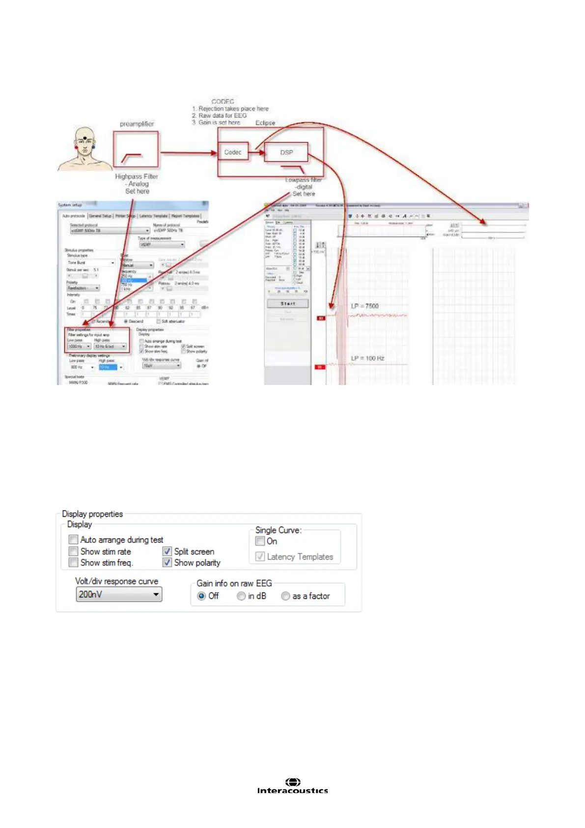
3.7.1.6 Display properties
From Display properties you can enable and disable the display of rearranged curves and split screen. You
can also set whether the stimulus rate, stimulus frequency, and stimulus polarity must be shown in the end of
each curve. When the parameters are enabled they will appear on the screen during measurement and on
the printout.
Setting the single curve option to On option will default the display screen to Single Curve mode, where only
one curve is displayed at a time. Enabling the Latency Templates option will display available latency tem-
plate data in edit mode whenever Single Curve display is used.
A preset Volt per division (unit gain) (Volt/Div response curve) can be set. Often 200nV is an appropriate
unit for display under normal ABR testing such as threshold and neurological.
 Loading...