6A – 2 GENERAL ENGINE MECHANICAL
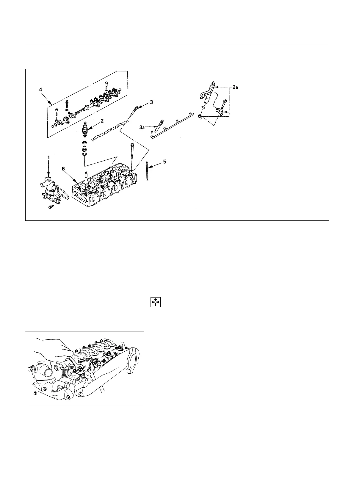
CYLINDER HEAD
NOTE:
• During disassembly, be sure that the valve train
components are kept together and identified so
that they can be re-installed in their original
locations.
• Before removing the cylinder head from the engine
and before disassembling the valve mechanism,
make a compression test and note the results.
DISASSEMBLY
1. Thermostat Housing Assembly
2. Injection Nozzle Holder (4JG2)
2a. Injection Nozzle Holder (4JB1, 4JB1TC)
1) Remove the nozzle holder bracket nuts.
6A-2-1.tif
6A-2-2.tif
(4JB1)
Disassembly steps
1. Thermostat housing Assembly
2. Injection nozzle holder (4JG2)
2a. Injection nozzle holder (4JB1
・
4JB1TC)
3. Glow plug and plug connector
(4JG2)
3a. Glow plug and plug connector
(4JB1
・
4JB1TC)
4. Rocker arm shaft and rocker arm
5. Push rod
6. Cylinder head
Reassembly steps
To reassemble, follow the
disassembly steps in the reverse
order.
 Loading...