FRONT AXLE
BX1870,BX2370,BX2670,LA203A,LA243A,RCK48(P),RCK54(P),RCK60B,RCK60D,RCK54D, WSM
3-S8
[3] DISASSEMBLING AND ASSEMBLING
(1) Front Axle Assembly
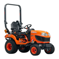
Power Steering Cylinder
1. Remove the cotter pin and remove the slotted nut for tie-rod (1).
2. Remove the power steering cylinder mounting screws and
remove the power steering cylinder (2) with tie-rod.
(When reassembling)
• Tighten the slotted nut to 18 N·m (1.8 kgf·m, 13 lbf·ft). If the
slot and pin hole do not meet, tighten the nut until they do
meet, and install the cotter pin.
• Be sure to split the cotter pin like an anchor.
9Y1210855FBS0013US0
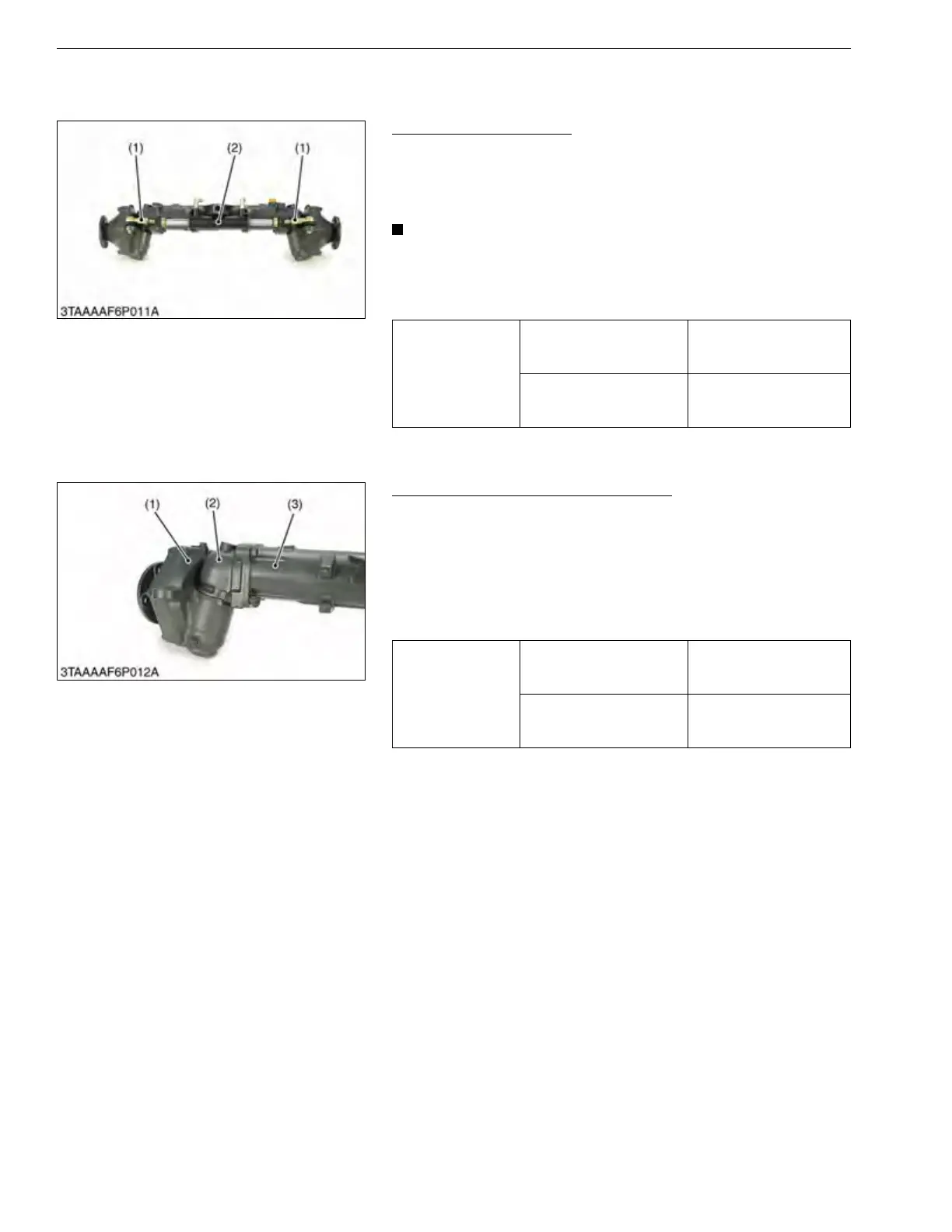
Bevel Gear Case and Front Gear Case
1. Remove the bevel gear case mounting screws.
2. Remove the bevel gear case (2) and front gear case (1) as a unit
from the front axle case (3).
(When reassembling)
• Apply grease to the O-ring and be careful not to damage it.
• Do not interchange right and left bevel gear case assemblies
and right and left gear case assemblies.
9Y1210855FBS0014US0
Tightening torque
Tie-rod slotted nut
18 to 34 N·m
1.8 to 3.5 kgf·m
13 to 25 lbf·ft
Power steering cylinder
mounting screw
48 to 55 N·m
4.9 to 5.7 kgf·m
36 to 41 lbf·ft
(1) Tie-rod (2) Power Steering Cylinder
Tightening torque
Bevel gear case mounting
screw (M10)
48 to 55 N·m
4.9 to 5.7 kgf·m
36 to 41 lbf·ft
Bevel gear case mounting
screw (M12)
78 to 90 N·m
7.9 to 9.2 kgf·m
58 to 66 lbf·ft
(1) Front Gear Case
(2) Bevel Gear Case
(3) Front Axle Case
 Loading...