ELECTRICAL SYSTEM
BX1870,BX2370,BX2670,LA203A,LA243A,RCK48(P),RCK54(P),RCK60B,RCK60D,RCK54D, WSM
6-S17
(10) Charging System
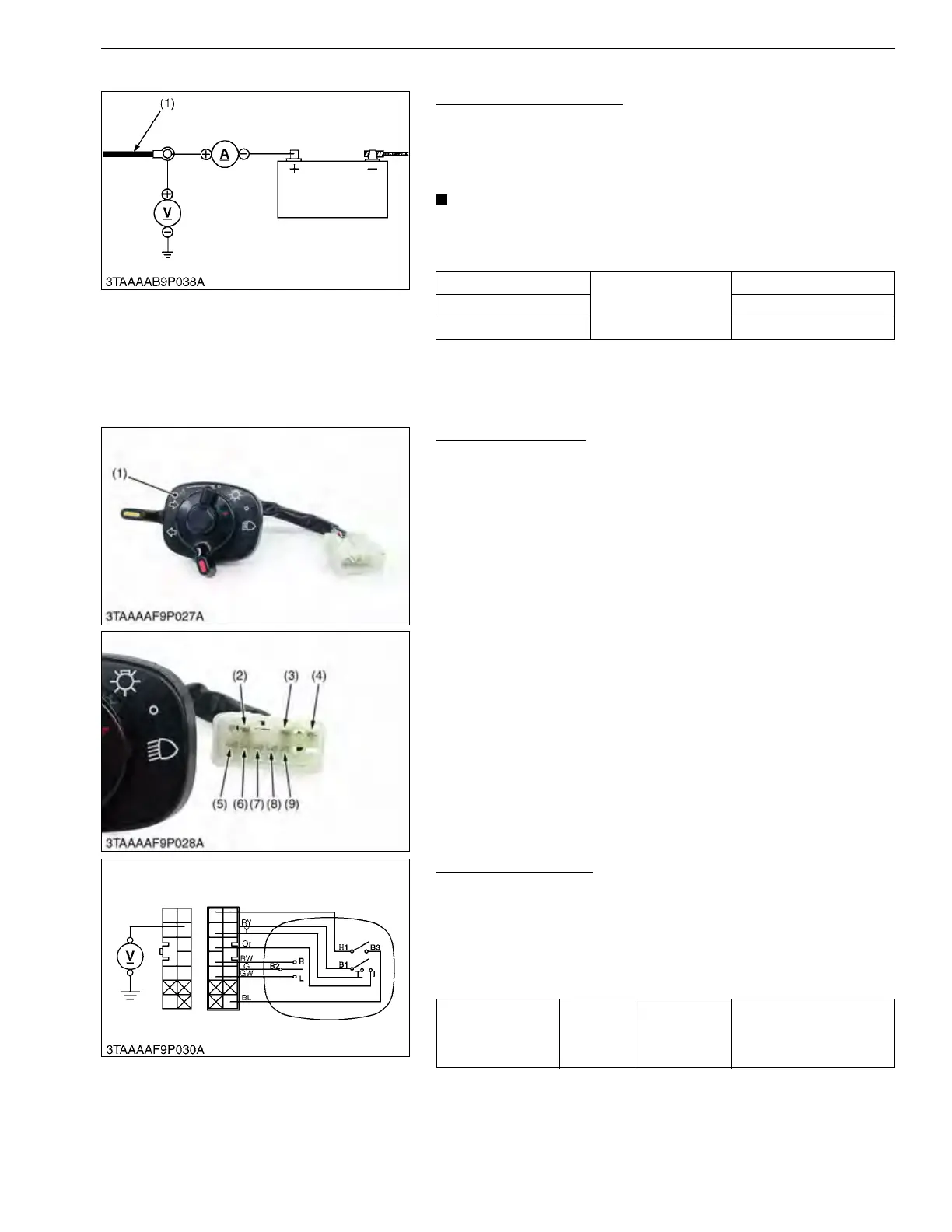
Battery Charging Current
1. After starting the engine, disconnect the battery positive cord
(+), and connect an ammeter and voltmeter. Then switch on all
electrical loads (such as head lights) and measure the charging
current.
• Connect an ammeter only after starting the engine.
• When the electrical loads is considerably low or the battery
is fully charged, the specified reading may not be obtained.
9Y1210855ELS0023US0
(11) Combination Switch
Combination Switch
1. Remove the meter panel, and disconnect the combination
switch connector.
2. Remove the combination switch (1) and perform the following
checks 1) to 8).
9Y1210855ELS0029US0
1) Connector Voltage
1. Connect the combination switch connector to the main wire
harness.
2. Measure the voltage with a voltmeter across the connector B1
terminal and chassis when the main switch is ON position.
3. If the voltage differs from the battery voltage, the wiring harness
and main switch is faulty.
9Y1210855ELS0030US0
Current
Factory specification
14 to 15 A
Voltage 14 to 15 V
Alternator speed 5200 min
-1
(rpm)
(1) Battery Positive Cord
(1) Combination Switch
(2) Red / Yellow Lead
(3) Green Lead
(4) Black / Blue Lead
(5) Blue / White Lead
(6) Yellow Lead
(7) Orange Lead
(8) Red / White Lead
(9) Green / White Lead
Voltage
Main
switch at
ON
position
B1 terminal –
Chassis
Battery voltage

 Loading...