ELECTRICAL SYSTEM
BX1870,BX2370,BX2670,LA203A,LA243A,RCK48(P),RCK54(P),RCK60B,RCK60D,RCK54D, WSM
6-S9
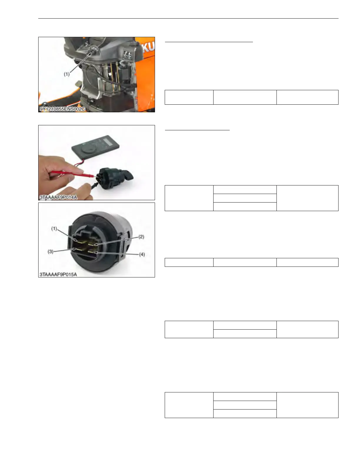
(2) Main Switch
Main Switch Connector Voltage
1. Remove the under cover panel.
2. Disconnect the 4P connector and remove the main switch (1).
3. Measure the voltage with a voltmeter across the connector 30
(red) terminal and chassis.
4. If the voltage differs from the battery voltage (11 to 14 V), the
wiring harness is faulty.
9Y1210855ELS0008US0
Main Switch Continuity
1) Main Switch Key at OFF Position
1. Set the main switch OFF position.
2. Measure the resistance with an ohmmeter across the B terminal
and the ACC terminal, B terminal and ST terminal, B terminal
and G terminal.
3. If infinity is not indicated, the contacts of the main switch are
faulty.
2) Main Switch Key at ON Position
1. Set the main switch ON position.
2. Measure the resistance with an ohmmeter across the B terminal
and the ACC terminal.
3. If 0 ohm is not indicated, the B – ACC contact of the main switch
are faulty.
3) Main Switch Key at PREHEAT Position
1. Set and hold the main switch key at the PREHEAT position.
2. Measure the resistance with an ohmmeter across the B terminal
and the G terminal, and measure the resistance across the B
terminal and the ACC terminal.
3. If 0 ohm is not indicated, these contacts of the main switch are
faulty.
4) Main Switch Key at START Position
1. Set and hold the main switch key at the START position.
2. Measure the resistance with an ohmmeter across the B terminal
and the G terminal, across the B terminal and the ST terminal,
and across the B terminal and the ACC terminal.
3. If 0 ohm is not indicated, these contacts of the main switch are
faulty.
9Y1210855ELS0009US0
Voltage
Connector 30 terminal –
chassis
Approx. battery voltage
(1) Main Switch
Resistance
B terminal – ACC terminal
InfinityB terminal – ST terminal
B terminal – G terminal
Resistance B terminal – ACC terminal 0 Ω
Resistance
B terminal – G terminal
0 Ω
B terminal – ACC terminal
Resistance
B terminal – G terminal
0 ΩB terminal – ST terminal
B terminal – ACC terminal
(1) B Terminal
(2) ST Terminal
(3) ACC Terminal
(4) G Terminal

 Loading...