STEERING
BX1870,BX2370,BX2670,LA203A,LA243A,RCK48(P),RCK54(P),RCK60B,RCK60D,RCK54D, WSM
4-S8
[3] DISASSEMBLING AND ASSEMBLING
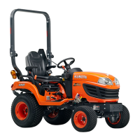
(1) Power Steering Cylinder
Adaptor and Tie-rod
1. Remove the cylinder hose adaptors (4), (6).
2. Remove the tie-rods (2), (8) from piston rod (7).
3. Remove the cylinder holder (1) and internal snap ring (3).
(When reassembling)
• Be sure to install the hose adaptors (4), (6) as shown figure left.
• After reassembling the tie-rod, be sure to adjust the toe-in. (See
page to 3-S4.)
9Y1210855STS0009US0
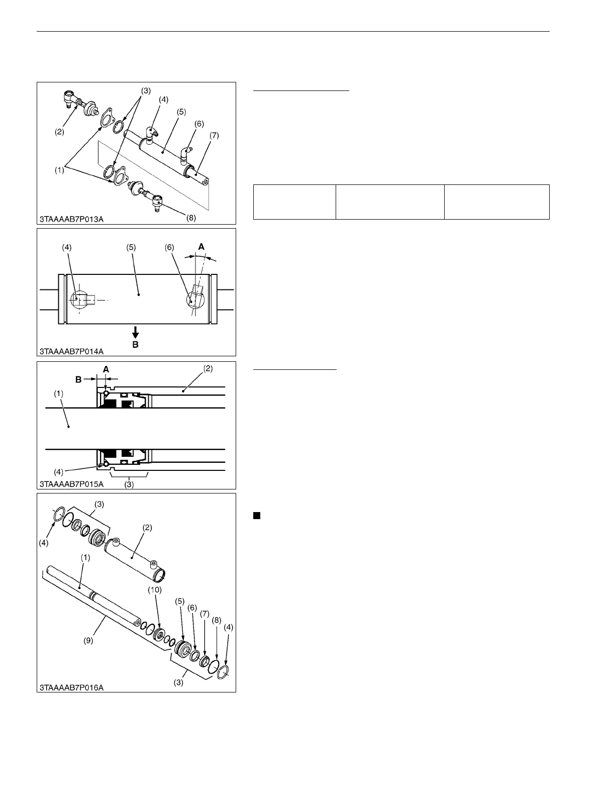
Steering Cylinder
1. Carefully clamp the cylinder in a vise.
2. Push one of the guide assembly (3) to inside of cylinder tube (2).
3. Drill a hole (2.5 mm dia., 0.098 in. dia.) on the cylinder tube (2)
just over the snap ring (4) as shown figure left.
4. Take a little screwdriver and lift off the snap ring (4) from its
groove. Simultaneousness support this action by pushing from
the outside of the cylinder tube with another little screwdriver or
another tool.
5. Push out the piston rod assembly (9) and take off the guide
assembly (3).
(When reassembling)
• Seals must be exchanged after disassembling.
• Apply transmission fluid to the exchanged seals.
• Enter the piston rod and block the guide assemblies with
the snap rings.
9Y1210855STS0010US0
Tightening torque Tie-rod screw
74 to 84 N·m
7.5 to 8.6 kgf·m
55 to 62 lbf·ft
(1) Cylinder Holder
(2) Tie-rod RH
(3) Internal Snap Ring
(4) Hose Adaptor RH
(5) Cylinder
(6) Hose Adaptor LH
(7) Piston Rod
(8) Tie-rod LH
A: 0.26 rad (15 °)
B: Front
(1) Piston Rod
(2) Cylinder Tube
(3) Guide Assembly
(4) Snap Ring
(5) Guide
(6) Seal Ring
(7) Wiper Ring
(8) O-ring
(9) Piston Rod Assembly
(10) Center Piston
A: Drill a Hole
B: 5.25 mm (0.207 in.)
 Loading...