Wiring of the system bus (CAN) / CANopen
8
Electrical installation
8.5
l
8.5-1
EDSPM-TXXX-3.0-04/2004
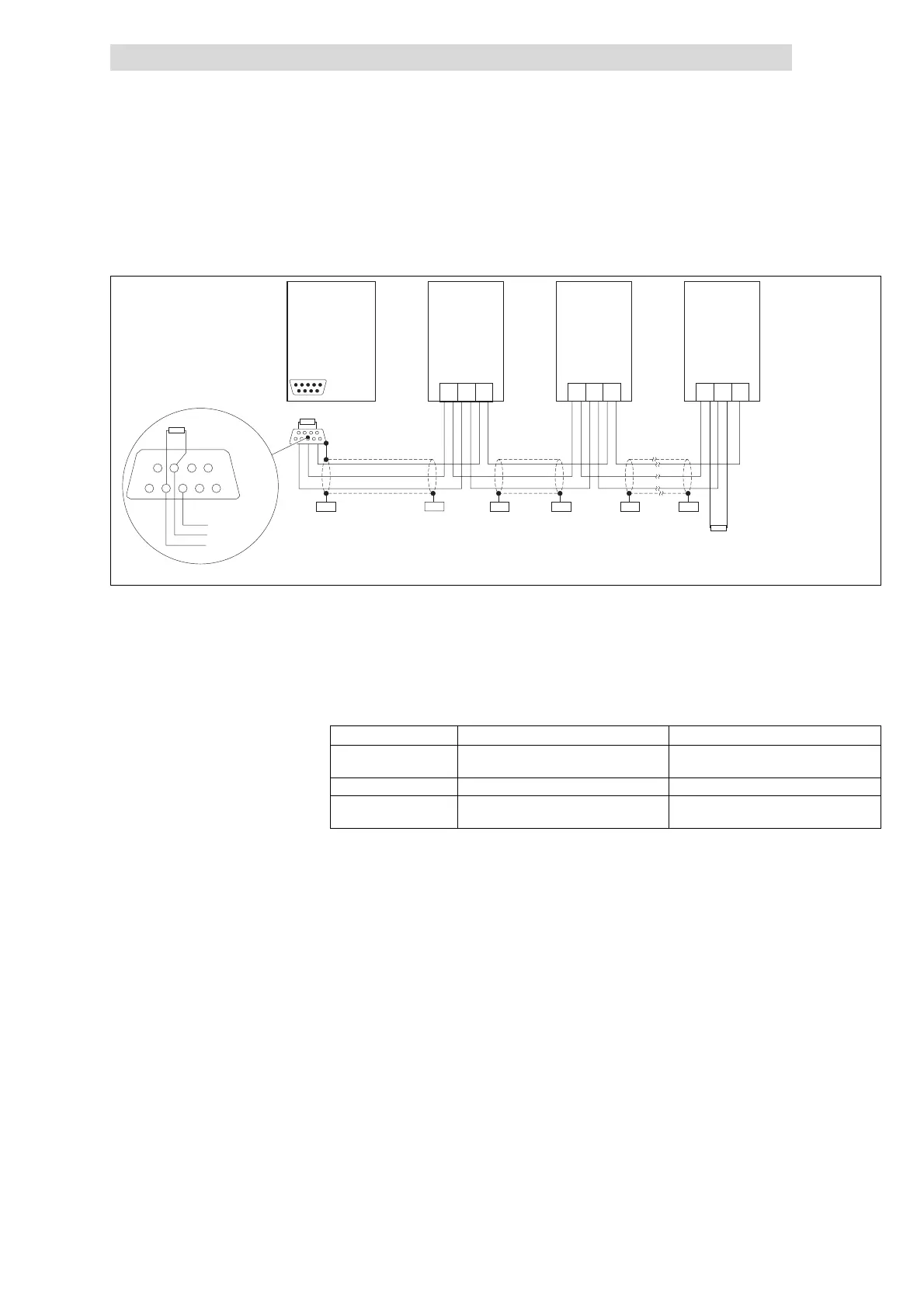
8.5 Wiring of the system bus (CAN) / CANopen
120
120
LO
LO LO
CG
CG CG
HI
HI HI
A
2
A
1
A
3
A
n
EPM-T110
EPM-T8XX
PES PES
PES
PES
PES
PES
CAN-GND
CAN-LOW
CAN-HIGH
120
1
2
3
4
5
6
7
8
9
epm-t061
Fig. 8.5-1 Basic wiring of the system bus (CAN) / CANopen
A1 Nodes 1 EPM-T110 or EPM- T8XX
A2 Node 2
A3 Node 3
A
n
Node n (e.g. PLC), n = max. 63
Please follow our recommendations on the use of the signal cable:
Total length ≤ 300 m ≤ 1000 m
Cable type LIYCY2x2x0.5mm
2
(twisted in pairs with shield)
CYPIMF2x2x0.5mm
2
(twisted in pairs with shield)
Cable resistance ≤ 80 Ω/km ≤ 80 Ω/km
Capacitance per unit
length
≤ 130 nF/km ≤ 60 nF/km
z
Connection of the bus terminating resistors:
– One resistor of 120 Ω eachatthefirstandlastbusnode
z
Communication protocol
– System bus (CAN) and
– CANopen (CAL-based communication profile DS301/DS401)
z
Bus extension:
– 25 m for max. 1 Mbit/s baud rate
– up to 1 km with reduced baud rate
z
Signal level acc. to ISO 11898
z
Up to 63 nodes possible
z
Access to all Lenze parameters
Features
 Loading...