16×dig. I/O compact (three-wire conductor)
6
The compact system
6.4
l
6.4-5
EDSPM-TXXX-3.0-04/2004
DI 8xDC24V
DIO/DO4/4xDC24V1A
L+
.0
.1
.2
.3
.4
.5
.6
.7
F
1
X4 X4–
2
3
4
5
6
7
8
9
10
L
PW
ER
RD
BA
ADR.
0
1
+
–
PE
X1
DC
24V
DI 8xDC24V
X 4x11COM
DIO 4xDC24V 1A
DO 4xDC24V 1A
0
X3
L+
.0
.1
.2
.3
.4
.5
.6
.7
F
1
X5 X6
X6–
2
3
4
5
6
7
8
9
10
5
EPM-T833 1A.10
21
3
4
epm-t045
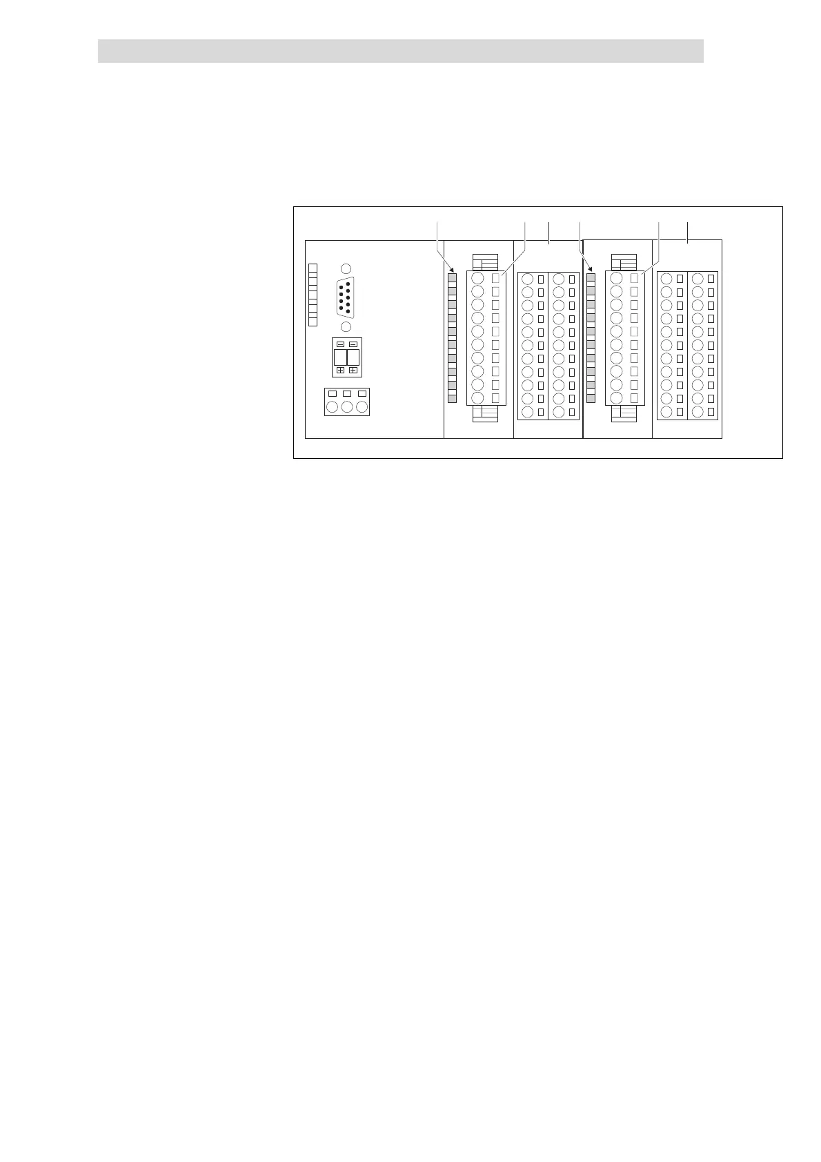
Fig. 6.4-4 Front view of 16×dig. I/O compact (three-wire conductor)
Status display for digital inputs / outputs at the terminal strips X3 and X5
L+ LED (yellow) is lit when the supply voltage is applied.
.0 ... .7 LED (green) is lit when the output is triggered and/or a HIGH
level is detected at the input
F LED (red) is lit in case of overload, overheating, short-circuit
errors.
Terminal strip X3 assignment
X3/1 Not assigned
X3/2 ... X3/9 Digital inputs E.0 ... E.7
X3/10 GND (reference potential)
Terminal strips (2 × 11 terminals)
X4 Electrically isolated terminal strip
X4– Terminal strip GND
Terminal strip X5 assignment
X5/1 DC 24 V supply voltage
X5/2 ... X5/5 Digital inputs/outputs E/A.0 ... E/A.3
X5/6 ... X5/9 Digital outputs A.4 ... A.7
X5/10 GND (reference potential)
Terminal strips (2 × 11 terminals)
X6 Electrically isolated terminal strip
X6– Terminal strip GND
Status display and terminal
assignment
 Loading...