Parameterising 2/4xcounter module
Encoder (modes 1, 3, and 5)
12
Parameter setting
12.4
12.4.4
l
12.4-9
EDSPM-TXXX-3.0-04/2004
epm-t141
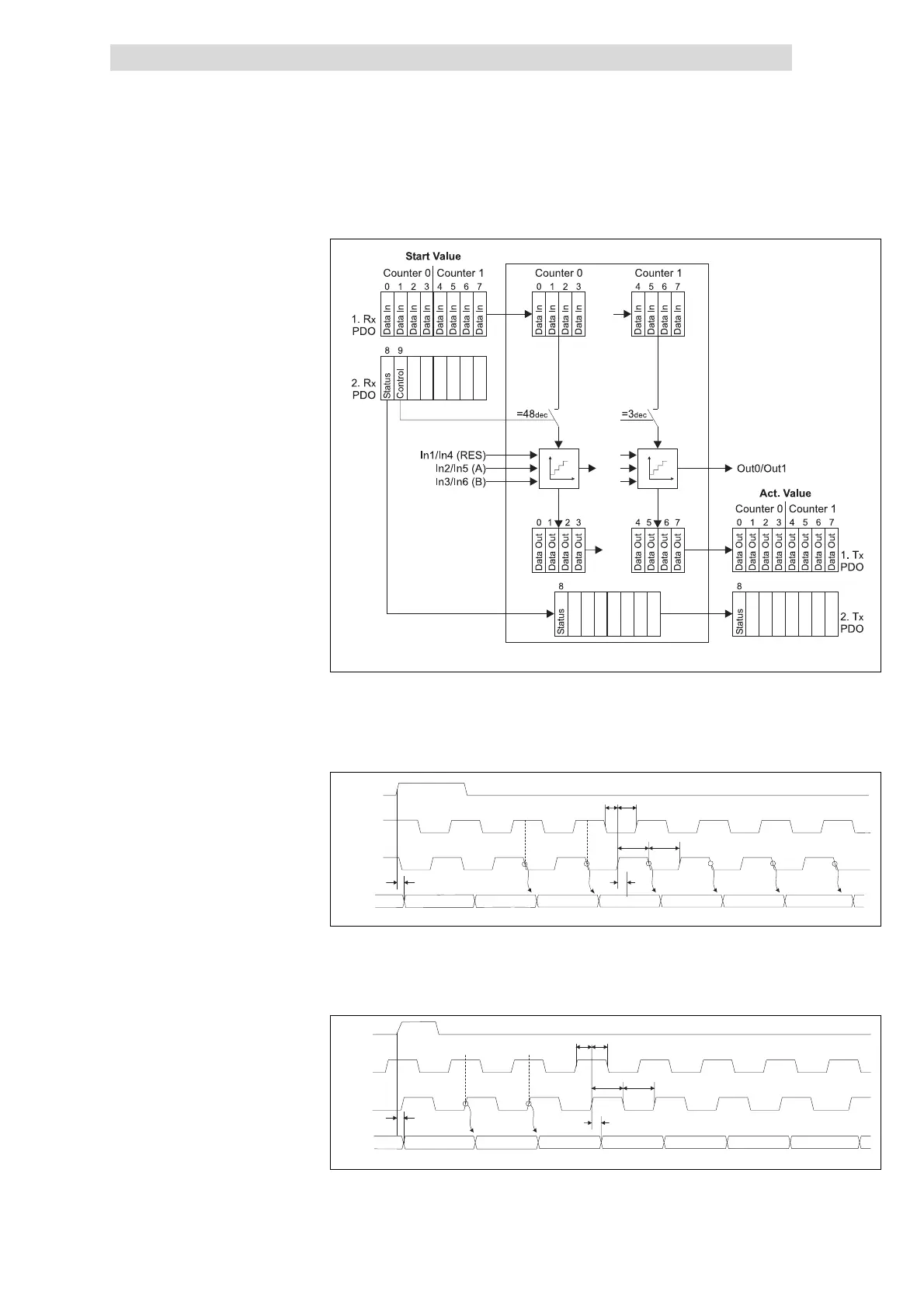
Fig. 12.4-9 Counter access of the 2/4xcounter in the modes 1, 3 and 5
Every HIGH-LOW edge at input IN2 / IN5 (A)increments the counter by 1 if a HIGH
level is applied to input IN3 / IN6 (B) at this time.
RES
B
A
Counter
0000 0000
XXXX
0000 0001 0000 0002
0000 0003
0000 0004 0000 0005 0000 0006
TreH2d
TcIH2d
TcIH
TdL2cIH TcIH2dH
TcIL
epm-t069
Fig. 12.4-10 Signal characteristic of 2/4xcounter in the mode 1 (upcounter)
Every LOW-HIGH edge at input IN2 / IN5 (A)decrements the counter by 1 if a HIGH
level is applied to input IN3 / IN6 (B) at this time.
RES
B
A
Counter
0000 0000XXXX
FFFF FFFF
FFFF FFFE
FFFF FFFD
FFFF FFFC
FFFF FFFB FFFF FFFA
TreH2d
TdL2cIH
Tt0H
TcIH2d
Tt0L
TcIH2dH
epm-t068
Fig. 12.4-11 Signal characteristic of 2/4xcounter in the mode 1 (downcounter)
Counter access
Signal characteristic in mode 1
 Loading...