Commissioning examples
I/O system IP20 at the 93xx controller
11
Commissioning
11.3
11.3.1
l
11.3-1
EDSPM-TXXX-3.0-04/2004
11.3 Commissioning examples
11.3.1 I/O system IP20 at the 93xx controller
An I/O system IP20 is to be operated on a controller of the 9300 series with six
digital inputs and two digital outputs.
z
The node address at the controller is 1. Hence, the node address at the I/O
system IP20 must be 2.
z
Thebaudrateistobe500kbits/s.
Stop!
When transmitting the status information of the I/O system IP20,
the complete byte is read into the controller, including the status
information of the digital outputs.
z
In the example, the input states are read via CAN-IN3.B0 ...
CAN-IN3.B5 and the output states via CAN-IN3.B6 and
CAN-IN3.B7.
z
Check the internal connection of the input signals CAN-IN3.B6
and CAN-IN3.B7 at the controller. Otherwise, outputs set (HIGH
level) at the I/O system may trigger uncontrolled actions of the
controller.
CAN
l
0
L
DIO 8xDC24V 1A
.0
L+
.1
.2
.3
.4
.5
.6
.7
F
1
2
3
4
5
6
7
8
9
L
10
EPM – T110 1A.10
EPM – T230 1A
PW
ER
RD
BA
ADR.
X1
1
2
0
2
+
–
DC
24V
–
+
Z
Z
DC 24 V
EPM-T110
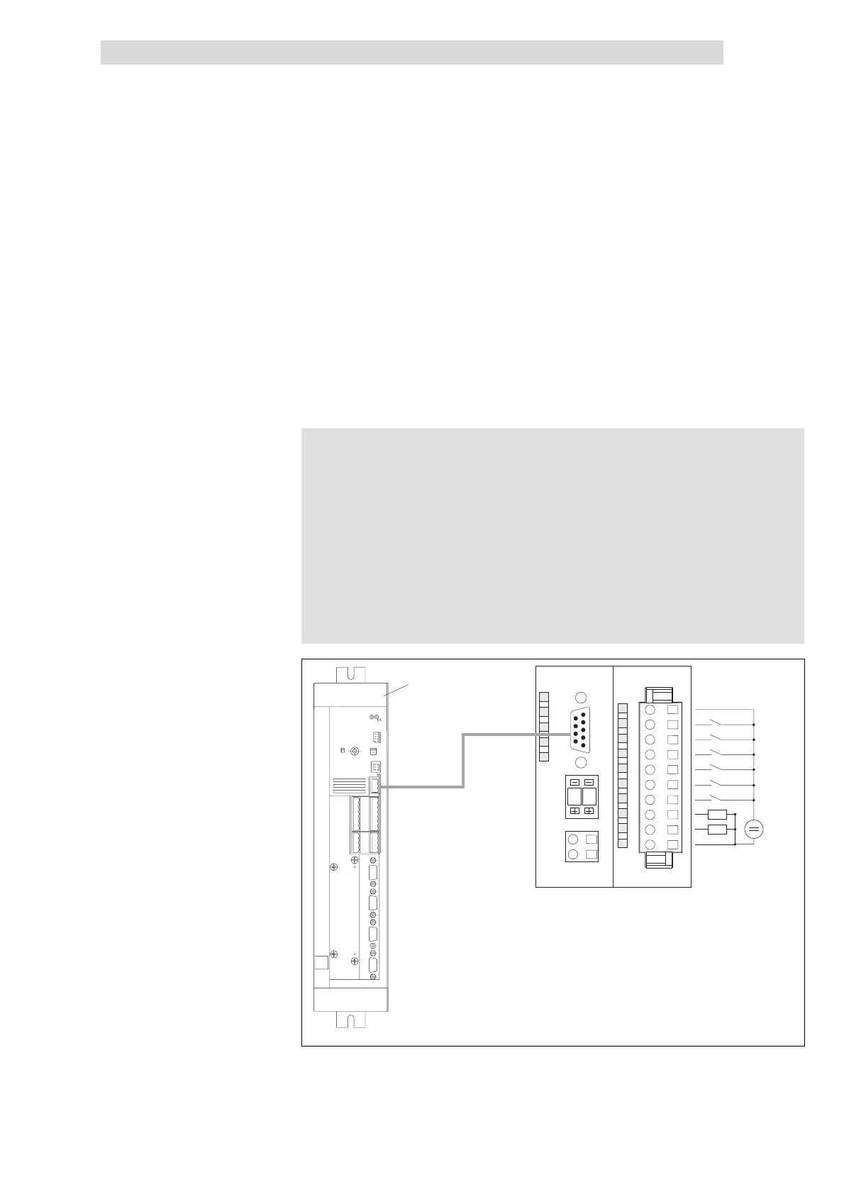
Fig. 11.3-1 9300 drive controller and I/O system IP20 with 6 digital inputs and 2 digital outputs
Drive controller 93XX
Example
 Loading...