EasyManua.ls Logo

Lenze EPM-T110 User Manual

Lenze EPM-T110
305 pages
To Next Page IconTo Next Page
To Previous Page IconTo Previous Page
Page #245 background imageLoading...
Page #245 background image
Parameterising 2/4xcounter module
2 × 32 bit counter with GATE and set/reset (modes 23 ... 26)
12
Parameter setting
12.4
12.4.13
l
12.4-35
EDSPM-TXXX-3.0-04/2004
12.4.13 2 × 32 bit counter with GATE and set/reset (modes 23 ... 26)
epm-t082
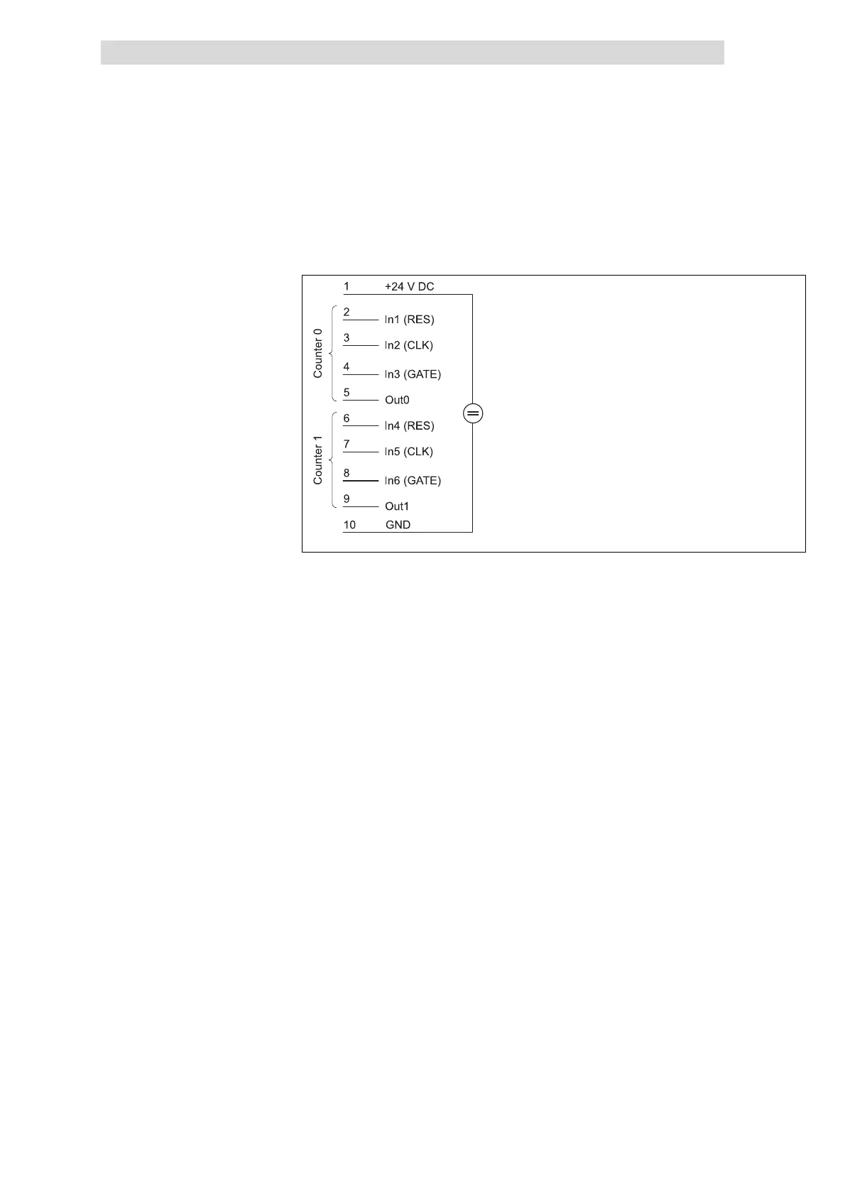
Fig. 12.4-45 Terminal assignment of the 2/4xcounter in the modes 23 ... 26
In the modes 23 to 26, two 32-bit counters are available, which are controlled via
a gate signal (gate). A starting value and a comparison value can be assigned to
each counter.
The modes differ in triggering the outputs Out0 / Out 1 differently (set or reset
function) and the counting direction:
Modes 23 and 25: Upcounter.
Modes 24 and 26: Downcounter
If a HIGH level is applied to input IN3 / IN6 (GATE), the counter is incremented or
decremented by 1 with each LOW/HIGH edge.
During the counting process, a LOW level must be applied to input IN1 / IN4 (RES).
A HIGH level deletes the counter.
Modes 23 and 24 (set function):
z
The signal at output OUT0 / OUT1 is set to HIGH level on counter loading.
z
When reaching the value loaded in Compare, the output signal is set to LOW
level. The counter continues to run.
Modes 25 and 26 (reset function):
z
The signal at output OUT0 / OUT1 is set to LOW level on counter loading.
z
When reaching the value loaded in Compare, the output signal is set to
HIGH level (modes 25 and 26). The counter continues to run.
Terminal assignment
GATE/CLK signal
RES signal
OUT signal
Show/Hide Bookmarks

Table of Contents

Question and Answer IconNeed help?

Do you have a question about the Lenze EPM-T110 and is the answer not in the manual?

Lenze EPM-T110 Specifications

General IconGeneral
BrandLenze
ModelEPM-T110
CategoryI/O Systems
LanguageEnglish

Summary

Safety instructions

Layout of the safety instructions

Explanation of the structure and symbols used for safety information in the manual.

Technical data

General data/operating conditions

Comprehensive technical specifications, standards, and operating parameters for the system.

The modular system

CAN gateway

Detailed description, features, and technical data of the CAN gateway module.

Electrical installation

Wiring according to EMC

Guidelines for proper wiring practices to ensure electromagnetic compatibility.

Connecting the supply voltage

Procedures for connecting the main power supply to the system.

Networking via system bus (CAN)

Networking via CANopen

Setting of baud rate and node address (node ID)

Procedure for configuring CANopen communication parameters.

Commissioning

Before switching on

Pre-operation checks and initialisation procedures before powering up the system.

Parameter setting

Parameterising analog modules

Configuration of analog modules, including signal functions and error behavior.

Parameterising 2/4xcounter module

Configuration options and modes for the 2/4xcounter module.

Troubleshooting and fault elimination

Fault messages

Table of common faults, their causes, and recommended remedies.

Related product manuals