Parameterising 2/4xcounter module
Measuring the pulse width, fref 50 kHz ( mode 6)
12
Parameter setting
12.4
12.4.5
l
12.4-12
EDSPM-TXXX-3.0-04/2004
12.4.5 Measuring the pulse width, f
ref
50 kHz (mode 6)
1
2
3
4
5
6
7
8
9
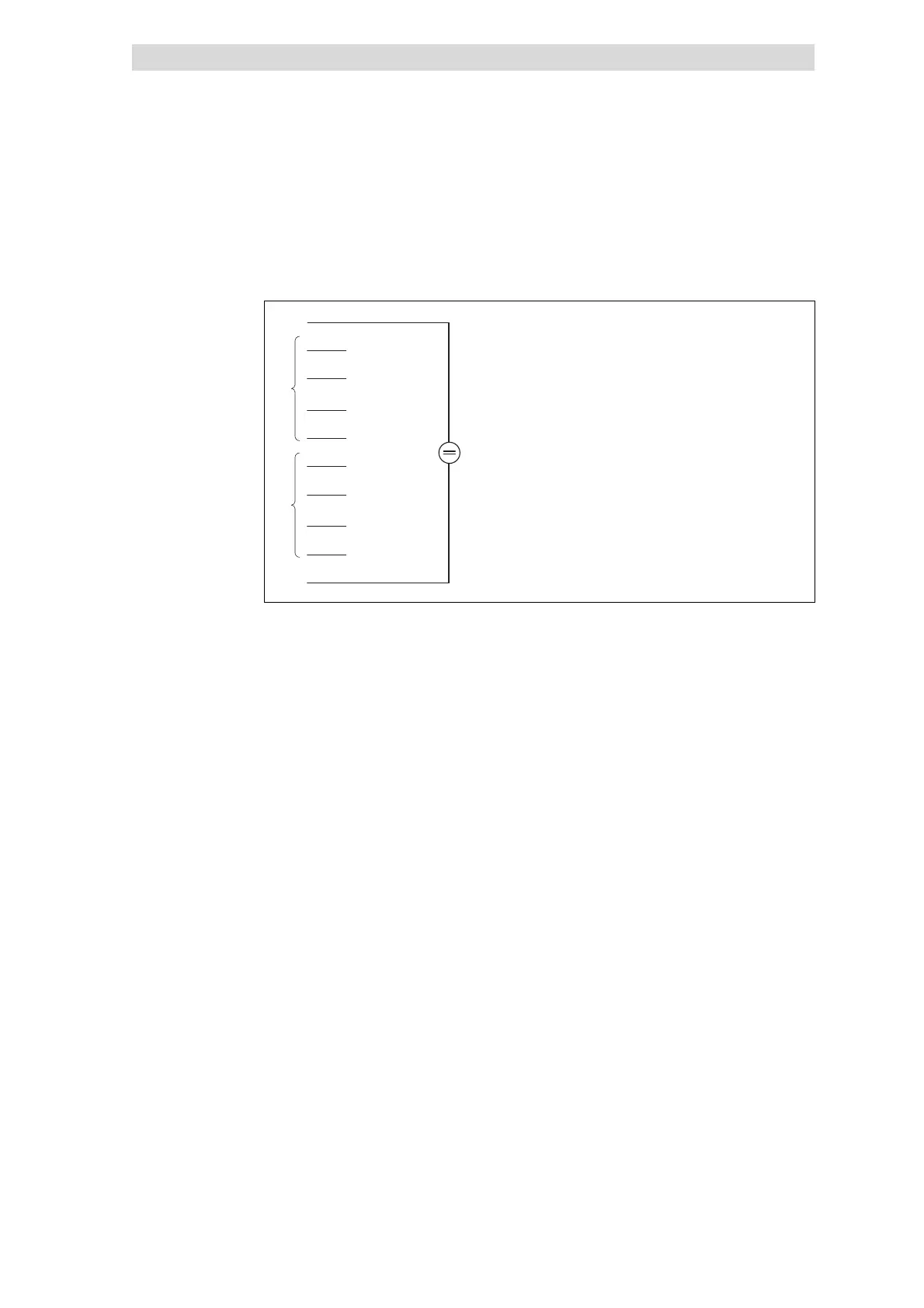
10 GND
+24VDC
In1 (RES)
In2 (PULSE)
In3 (DIR)
Out0
In4 (RES)
In5 (PULSE)
In6 (DIR)
Out1
Counter 0
Counter 1
epm-t075
Fig. 12.4-16 Terminal assignment of the 2/4xcounter in the mode 6
The pulse widths of the signals at input IN2 / IN5 (PULSE) are measured with an
internal time base.
The measuring process starts with a HIGH-LOW edge at input IN2 / IN5 (PULSE)
and ends with the LOW-HIGH edge.
A LOW-HIGH edge of the measured signal stores the pulse width with the unit
20 ms (corresponds to a clock frequency of f
ref
= 50 kHz; the clock frequency
cannot be changed). This result is available in the data output range and can be
read out until the next new result.
The counting direction is determined via the signal level at input IN3 / IN6 (DIR):
Upcounter: LOW level
Downcounter: HIGH level
During the counting process, a LOW level must be applied to input IN1 / IN4 (RES).
A HIGH level deletes the counter.
Output OUT0 / OUT1 has no function.
Terminal assignment
PULSE signal
DIR signal
RES signal
OUT signal
 Loading...