Transmitting process data
Process image of the modular system
10
Network via CANopen
10.4
10.4.5
l
10.4-6
EDSPM-TXXX-3.0-04/2004
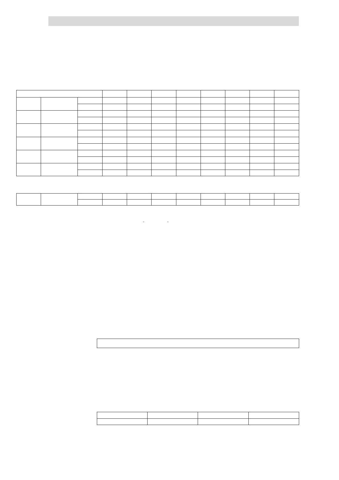
Process image
Byte 0 Byte 1 Byte 2 Byte 3 Byte 4 Byte 5 Byte 6 Byte 7
Fixed
or
he
irs
PDO1-RX M6 – – – – – – –
PDO1
DIO
PDO1-TX M1 M2 M3 M4 M5 M5 – –
Fixed
or
he
irs
PDO2-RX M8 M8 M8 M8 M8 M8 M8 M8
PDO2
AIO
PDO2-TX M7 M7 M7 M7 M7 M7 M7 M7
PDO3-RX M8 M8 M11 M11 M11 M11 – –
PDO3 DIO or AIO
1)
PDO3-TX M8 M8 M8 M8 M8 M8 M8 M8
PDO4-RX – – – – – – – –
PDO4 DIO or AIO
1)
PDO4-TX M8 M8 M11 M11 M11 M11 – –
PDO5-Rx M10 M10 M10 M10 M10 M10 – –
PDO5 DIO or AIO
1)
PDO5-Tx M10 M10 M10 M10 M10 M10 – –
PDO6-Rx M9 M9 M9 M9 – – – –
PDO6 DIO or AIO
1)
PDO6-Tx M9 M9 M9 M9 – – – –
... ... ... ... ... ... ... ... ... ... ...
PDO10-RX – – – – – – – –
PDO10 DIO or
IO
PDO10-TX – – – – – – – –
1)
A PDO can be either assigned to AIO or DIO. AI Analog input data
The modules are assigned according to the slot
AO Analog output data
sequence, with the DIO being assigned fir st.
DI Digital input data
DO Digital output data
AIO A nalog input and output data
DIO Digital input and output da ta
Specialfeatures of the modules 1×counter/16×digital input and SSI interface:
z
Themodule1×counter/16×digital input always assigns the next to last and
theSSIinterfacemodulealwaysthelastofthePDOsused.
z
The modules cannot be assigned to PDO1 and PDO2. Thus, only eight of
these modules can be used in a system.
z
The modules assign a whole PDO (8 bytes) each.
The transmission times of the input / output signals within the I/O system IP20 can
be calculated with a formula.
t
t
= t
c
+ (N
PDOTX
⋅ 8 ms) + (N
PDORX
⋅ 2 ms) + t
d
+ 742 ms
t
t
Transmission time of input / output signals of a module between
fieldbus connection and input / output terminals.
t
c
Time required for copying into the CAN object directory
N
PDOTX
Transmitting the PDO number (PDO1-Tx ... PDO10-Tx)
N
PDORX
Receiving the PDO number (PDO1-Rx ... PDO10-Rx)
t
d
Module delay time
742 µs Fixed internal processing time
Time required for copying into the CAN object directory:
DO modules DI modules AO modules AI modules
t
c
=50µs+n×14µs t
c
=50µs+n×25µs t
c
=50µs + n × 210 µs t
c
=50µs + n × 250 µs
n Number of bytes assigned by the module in the PDOs
Transmission times
 Loading...