Wiring the standard device
Wiring of system bus (CAN)
5
5.10
5.10-1
EDSVF9333V EN 3.0-06/2005
5.10 Wiring of system bus (CAN)
A
1
A
2
A
3
A
n
93XX 93XX 93XX
GND GND GND GNDLO LO LO LOHI HI HI HIX4 X4 X4PE PE PE PE
120 120
9300VEC054
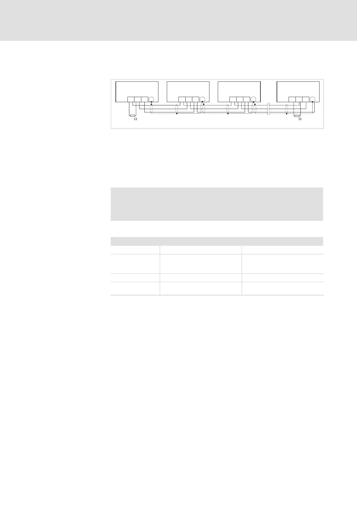
Fig. 5.10-1 System bus (CAN) wiring
A
1
Bus device 1 (controller)
A
2
Bus device 2 (controller)
A
3
Bus device 3 (controller)
A
n
Busdevicen(e.g.PLC),n=max.63
X4/GND CAN-GND: System bus reference potential
X4/LO CAN-LOW: System bus LOW (data line)
X4/HI CAN-HIGH: System bus HIGH (data line)
Stop!
Connect a 120-Ω terminating resistor to the first and last node
between the terminals CAN-LOW and CAN-HIGH.
For trouble-free operation, use cables with the listed specifications:
Cable specifications
Overall length ≤ 300 m
≤ 1000 m
Cable type LIYCY2x2x0.5mm
2
(twisted in pairs and shielded
cores)
CYPIMF2x2x0.5mm
2
(twisted in pairs and shielded
cores)
Specific resistance ≤ 80 Ω/km ≤ 80 Ω/km
Capacitance per unit
length
≤ 130 nF/km ≤ 60 nF/km
Wiring
 Loading...