Safe standstill
Connecting relay K
SR
11
11.3
11.3-1
EDSVF9333V EN 3.0-06/2005
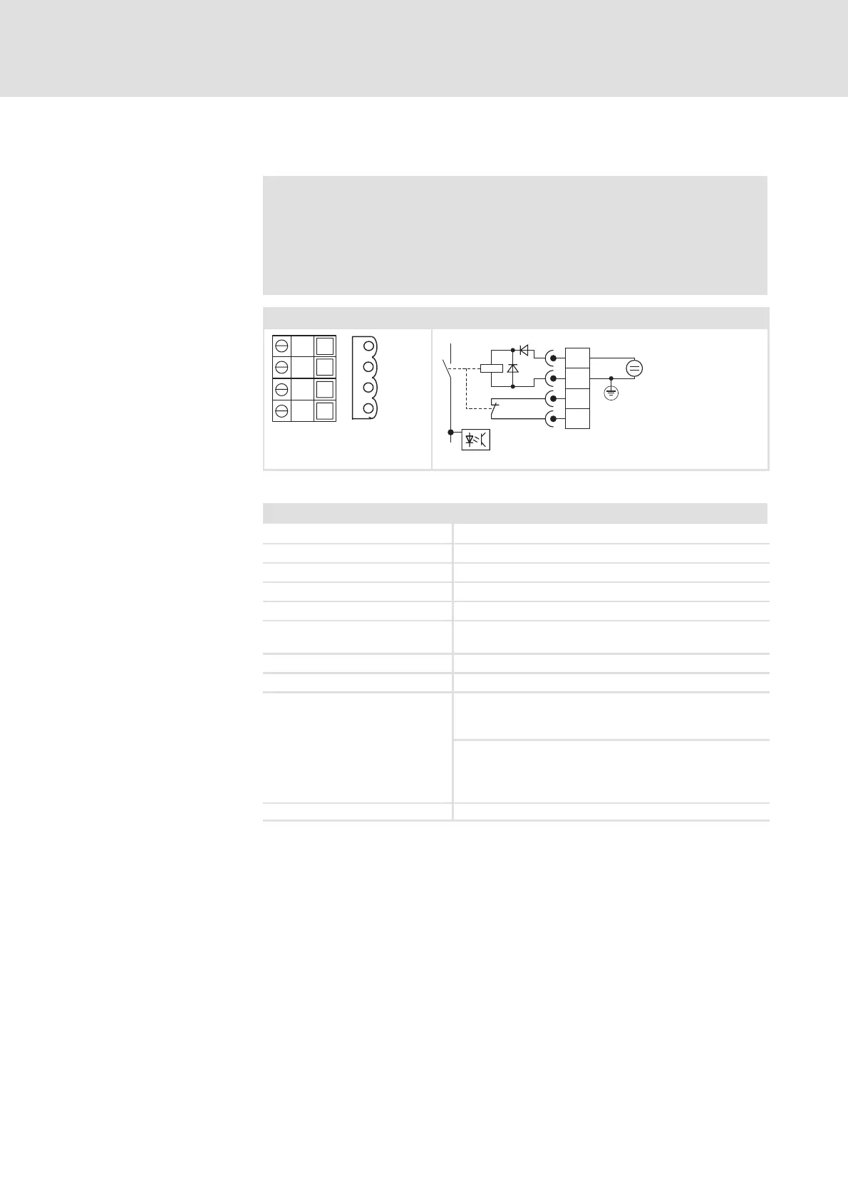
11.3 Connecting relay K
SR
Danger!
The electrical reference point for the coil of the safety relay K
SR
must be connected to the PE conductor system (DIN EN 60204-1
paragraph 9.4.3)!
This is the only way to protect the unit from earth faults.
Terminal strip X11 Internal wiring / wiring of terminal strip X11
3 4
3 3
K 3 2
K 3 1
3 43 3K 3 2
K 3 1
DC 24 V
X11
34
33
K32
K31
+5 V
+
+
–
K
SR
9300vec103
Fig. 11.3-1 Safety relay K
SR
Field Values
Coil voltage at +20 °C DC 24 V (20 ... 30 V)
Coil resistance at +20 °C 823 Ω ±10 %
Rated coil power approx. 700 mW
Max. switching voltage AC 250 V, DC 250 V (0.45 A)
Max. AC switching capacity 1500 VA
Max. switching current (ohmic
load)
AC 6 A (250 V), DC 6 A (50 V)
Recommended minimum load >50mW
Max. switching rate 6 switchings per minute
Electrical service life
10
5
switching cycle at 6 A
10
6
switching cycles at 1 A
107 switching cycles at 0.25 A
at 250 V AC
(ohmic load)
6×10
3
switching cycles at 6 A
10
6
switching cycles at 3 A
1.5×10
6
switching cycles at 1 A
107 switching cycles at 0.1 A
at 24 V DC
(ohmic load)
Mechanical life time 10
7
switching cycles
Technical data
 Loading...