Configuration
Code table
8
8.3
8.3-50
EDSVF9333V EN 3.0-06/2005
IMPORTANTPossible settingsCode
SelectionLenzeNameNo.
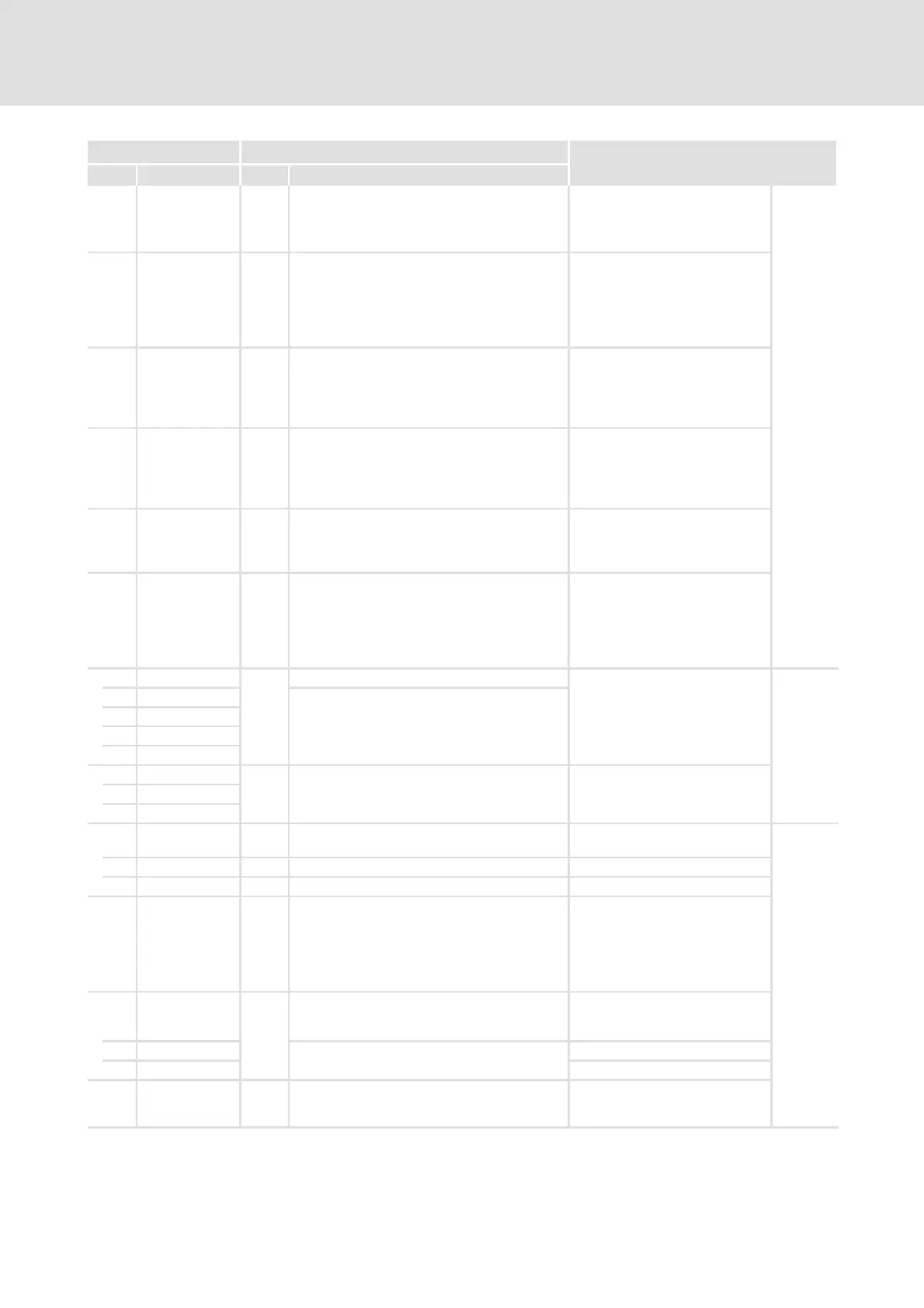
C0800
CFG: SET 1000 FIXED0% Selection list 1 Configuration of analog input
signal, function block PCTRL
z Input for the process setpoint
z Value range: ±200 %
See System
Manual
(extension)
C0801
CFG: ACT 1000 FIXED0% Selection list 1 Configuration of analog input
signal, function block PCTRL
Configuration of analog input
signal of PCTRL1
z Input for the actual value
z Value range: ±200 %
C0802
CFG: INFLU 1000 FIXED0% Selection list 1 Configuration of analog input
signal, function block PCTRL
z Evaluation (influence) of the
output signal
z Value range: ±200 %
C0803
CFG: ADAPT 1000 FIXED0% Selection list 1 Configuration of analog input
signal, function block PCTRL
z The gain V
p
can be changed via
the adaptation input
z Value range: ±200 %
C0804
CFG: INACT 1000 FIXED0 Selection list 2 Configuration of digital input
signal, function block PCTRL
z HIGH = deactivates the process
controller
C0805
CFG: I-OFF 1000 FIXED0 Selection list 2 Configuration of digital input
signal, function block PCTRL
z HIGH = Switching off integral
action component
z LOW = Switching on integral
action component
C0808 -199.99 {0.01 %} 199.99
Function block PCTRL
z Display of the signals linked in
C0801, C0802, C0803 and
C0804
See System
Manual
(extension)
1 DIS: SET
2 DIS: ACT
3 DIS: INFLU
4 DIS: ADAPT
C0809
Function block PCTRL
z Display of the signals linked in
C0805 and C0806
1 DIS: INACT
2 DIS: I-OFF
C0810
Selection list 1 Configuration of analog input
signals, function block ASW1
See System
Manual
(extension)
1 CFG: IN 1000 FIXED0% ASW1-IN1
2 CFG: IN 1000 FIXED0% ASW1-IN2
C0811
CFG: SET 1000 FIXED0 Selection list 2 Configuration of digital input
signal, function block ASW1
z LOW: signal at ASW1-IN1 is
output to ASW1-OUT
z HIGH: signal at ASW1-IN2 is
output to ASW1-OUT
C0812 -199.99 {0.01 %} 199.99 Function block ASW1
z Display of the signals linked in
C0810
1 DIS: IN ASW1-IN1
2 DIS: IN ASW1-IN2
C0813 DIS: SET 0 1 Function block ASW1
z Display of the signal linked in
C0811
 Loading...