Installing the basic device
Basic devices in the power range 45 ... 55 kW
Thermally separated mounting (push-through technique)
4
4.3
4.3.3
4.3-3
EDSVF9333V EN 3.0-06/2005
4.3.3 Thermally separated mounting (push-through technique)
For mounting in push-through technique, the drive controller of type
EVF93xx-EV must be used. In addition, the mounting set for E J0010
push-through technique is required.
d2
d2
d2
d
b
g
a1
a
d1
b1
h
h
c1
c2
c3
c4
e
e1
L
9300vec117
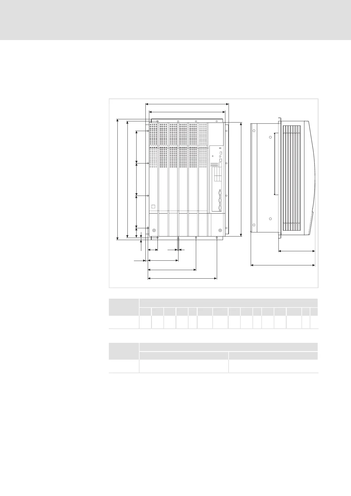
Fig. 4.3-2 Dimensions for thermally separated m ounting 45 ... 55 kW
9300 vector Dimensions [mm]
Type a a1 b b1 c1 c2 c3 c4 d d1 d2 e
1)
e1 g h
EVF9330-EV
EVF9331-EV
373 340 543 510 45 137.5 217.5 310 525 45 145 285 163.5 7 9
1)
For a fieldbus module plugged onto X1, consider mounting space for connecting cables
9300 vector Dimensions [mm]
Type Width Height
EVF9330-EV
EVF9331-EV
320 492
Dimensions
Mounting cutout in control
cabinet
 Loading...