Safe standstill
Operating mode
11
11.2
11.2-1
EDSVF9333V EN 3.0-06/2005
11.2 Operating mode
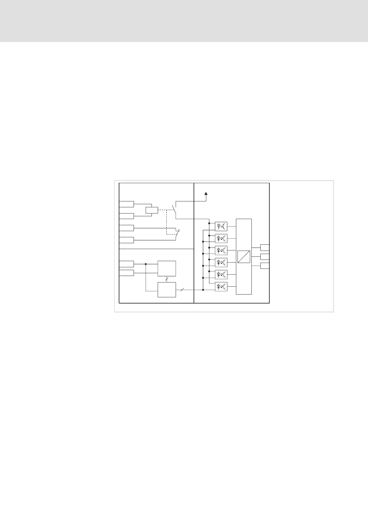
The ”safe standstill” circuit is created with a forcibly guided safety relay
inside the controller. This relay disconnects the supply of the drivers for
transmitting the pulse pattern to the power output stage. Three areas must
be observed for the implementation:
ƒ Pulse release via safety relay K
SR
– Input for switching the safety relay
– Forcibly guided feedback for monitoring
ƒ Digital input X5/28 (controller enable) with optional feedback via the
digital output DIGOUT
ƒ Power output stage
X11/34
X11/33
X11/K32
X11/K31
X5/28
5V
µC
PWM
PWM
-
~
U
V
W
DIGOUT
K
SR
9300vec100
Fig. 11.2-1 Internal circuit of the ”safe standstill” function with three isolated circuit areas
c Area 1: Safety relay K
SR
, pulse release and feedback
d Area 2: Controller enable, circuit for the internal control
e Area 3: Power output stage
Internal wiring
 Loading...