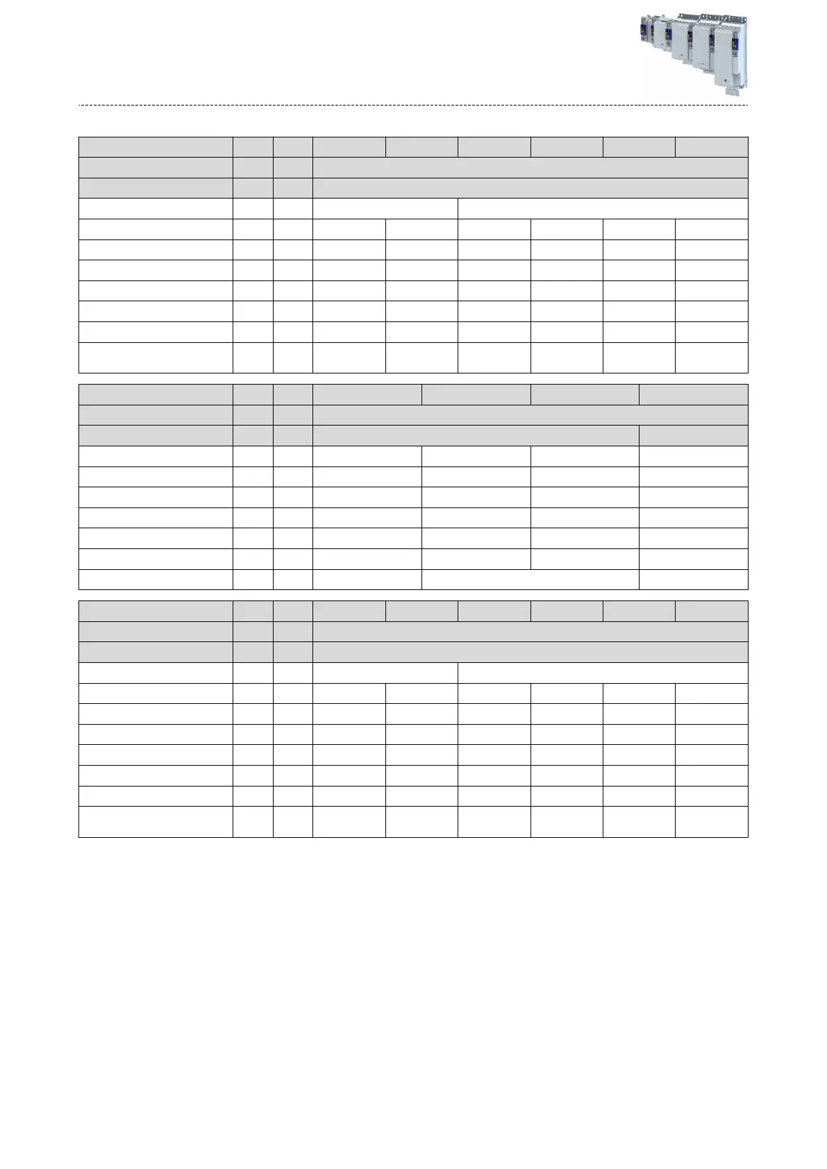
Terminal data
Rated power P
r
ated
kW 0.55 ... 4 7.5 ... 15 22 30 ... 45 55 ... 75 90 ... 110
Connecon descripon Mains connecon
Connecon X100
Connecon type Pluggable Non-pluggable
Max. cable cross-secon mm² 2.5 16 35 50 95 150
Max. cable cross-secon AWG 12 6 2 1/0 4/0 -
Stripping length mm 8 14 18 19 22 28
Stripping length in 0.3 0.55 0.7 0.75 0.87 1.1
Tightening torque Nm 0.5 1.8 3.8 4 10 18
Tightening torque lb-in 4.4 16 34 35 89 160
Required tool Screwdriver
0.5 x 3.0
Screwdriver
0.8 x 4.0
Screwdriver
0.8 x 5.5
Hex key 5.0 Hex key 6.0 Hex key 8.0
Rated power P
r
ated
kW 0.55 ... 4 7.5 ... 15 22 ... 75 90 ... 110
Connecon descripon PE connecon
Connecon PE screw PE bolt
Max. cable cross-secon mm² 6 16 25 150
Max. cable cross-secon AWG 10 6 2 300 kcmil
Stripping length mm 10 11 16 -
Stripping length in 0.4 0.4 0.6 -
Tightening torque Nm 2 3.4 4 10
Tightening torque lb-in 18 30 35 89
Required tool Torx key 20 Crossp screwdriver PZ2 Wrench size 13
Rated power P
r
ated
kW 0.55 ... 4 7.5 ... 15 22 30 ... 45 55 ... 75 90 ... 110
Connecon descripon Motor connecon
Connecon X105
Connecon type Pluggable Non-pluggable
Max. cable cross-secon mm² 2.5 16 35 50 95 150
Max. cable cross-secon AWG 12 6 2 1/0 4/0 -
Stripping length mm 8 14 18 19 22 28
Stripping length in 0.3 0.55 0.7 0.75 0.87 1.1
Tightening torque Nm 0.5 1.8 3.8 4 10 18
Tightening torque lb-in 4.4 16 34 35 89 160
Required tool Screwdriver
0.5 x 3.0
Screwdriver
0.8 x 4.0
Screwdriver
0.8 x 5.5
Hex key 5.0 Hex key 6.0 Hex key 8.0
The terminal data for the terminal X1 can be found under:4Basic Sa
fety - STO ^ 161
The terminal data for the terminals X82 and X83 can be found under: 4Terminal data ^ 165
Electrical ins
tallaon
Mains connecon
3-phase mains connecon 400 V
142