9.6.4 Compensaon of
runme delays
In reality, both the input circuit in the servo inverter and the touch probe sensor have runme
delays (latencies) themselves. These can be taken into account in the calculaon of the real
trigger me and thus the real posion at the trigger me.
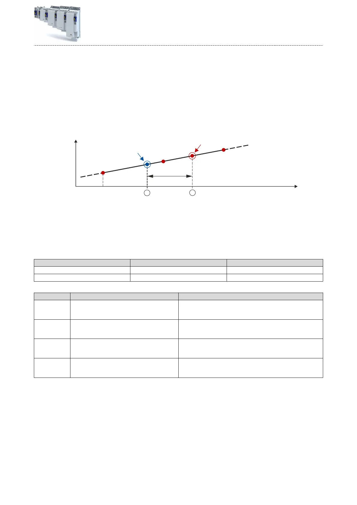
In the following gure, the event is detected in the servo inverter at the me ②. Due to the
input circuit and the sensor used, the signal runme, however, has been delayed. The real
physical event has already occurred at me ①. For compensang this runme delay, you can
set a corresponding delay me for each touch probe channel that is included in the determi-
naon of the control cycle and interpolaon of the posion, see gure in chapter "General
mode of operaon". ^ 142
1
2
p
n-1
p
n-2
Position
t
Event received
Event
Delay time
p
n
"Delay
me":
Delay
me between the real physical event and the electrical detecon.
①
Real physical event
②
Electrical detecon of the event in the servo inverter
Delay mes of the digital input and the required minimum signal duraon
The following table lists the typical delay mes and the required minimum signal duraons for
the digital inputs of the servo inverter:
Digital signal Typical delay me Minimum signal duraon
Rising edge (HIGH pulse) 4 µs 4 µs
Falling edge (LOW pulse) 4 µs 4 µs
Parameter
Address Name / seng range / [default seng] Info
0x2D00:001 Touch probe (TP) delay me: Touch probe 1 delay
me
0.000 ... [0.000] ... 7.000
ms
Seng of the delay me for touch probe 1.
0x2D00:002 Touch probe (TP) delay me: Touch probe 2 delay
me
0.000 ... [0.000] ... 7.000 ms
Seng of the delay me for touch probe 2.
0x2D00:003 Touch probe (TP) delay me: Touch probe 3 delay
me
0.000 ... [0.000] ... 7.000 ms
Seng of the delay me for touch probe 3.
0x2D00:004 Touch probe (TP) delay me: Touch probe 4 delay
me
0.000 ... [0.000] ... 7.000 ms
Seng of the delay me for touch probe 4.
Congure posion control
Posion
detecon with touch probe (TP)
Compensaon of runme delays
143
 Loading...


