13.9.1.1 Parameters for the thermal model
The introducon of a two-component model with two me constants (one for the winding
and the other f
or the housing/laminated core) serves to display the thermal behaviour of the
motors up to 500% of the rated current.
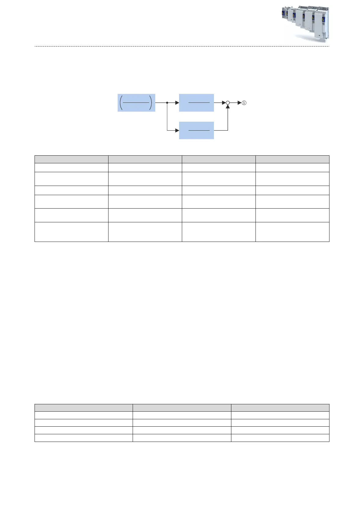
Structure of the monitoring
2
(1 + p )τ
2
1
k
2
(1 + p )τ
1
1
k
1
I
act Motor
I (n)
perm Motor
①
Thermal ulisaon of the motor in [%]
Parameter Symbol Descripon Dimension unit
- I
actMot
or
Actual motor current A
- I
permMotor
Permissible motor current (speed-
dependent)
A
0x2D4C:001 τ
1
Therm. me constant of winding s
0x2D4C:002 τ
2
Therm. me constant of laminated
core
s
0x2D4C:003 k
1
Percentage of the winding in the
nal temperature
%
- k
2
Percentage of the laminated core in
the nal temperature: k2 = 100 % -
k1
%
Calculaon with only one me constant
If k1 = "0 %" is set, the part of the winding is not taken into consideraon and the thermal
model is only c
alculated using the me constant set for the housing/laminated core. This set-
ting is e.g. required if only the me constant of the laminated core (T2) is known.
Parameter seng of the me constant and the inuence of the winding on motors of other manufacturers
When the inuence of the winding is acvated, the i
2
xt monitoring becomes more sensible as
if only the inuence of the laminated core would be used for monitoring purposes.
The necessity to acvate the inuence of the winding rises with the increasing ulisaon of
the motor overload capacity. It also rises with applicaons where the motor is at standsll for
longer periods or cyclically and a load ≥ permanent standsll current is applied.
For determining the values for the thermal me constant, try to get the data from the motor
manufacturer. If this is not possible, you can use the data of a comparable Lenze motor.
Condions for comparability are similar values in case of the following motor features:
•
Squar
e dimensions of the motor (acve part)
•
Leng
th of the acve part (if available)
•
Permanent standsll current Io [A_RMS]
•
Peak current/overload capacity [A_RMS]
•
Copper resistance of the winding at 20 °C [Rphase]
Example:
Motor features Data of the third-party motor Descripon
Square dimension 95 mm MCS09xxx = 89 mm
Standsll current 2.2 A MCS09F38 = 3.0 A
Peak current 7.3 A MCS09F38 = 15 A
Phase resistance 5.1 Ohms MCS09F38 = 5.2 Ohms
Conguring the motor control
Mot
or protecon
Motor overload monitoring (i²*t)
266
 Loading...


