 Loading...
Do you have a question about the Lenze I95AE240F and is the answer not in the manual?
Covers personnel qualifications and responsibilities for safe product operation, and process engineering considerations.
Defines the conditions and directives for operating the product correctly and safely, including compliance with EU directives.
Identifies potential hazards associated with the product, including electrostatic sensitive devices, electrical voltage, leakage current, hot surfaces, and motor protection.
Provides critical safety notes and prerequisites for commissioning, including wiring, motor connection, and emergency off functions.
Details the default mapping for the cyclic sync position mode, including parameters received from the controller and sent to the controller.
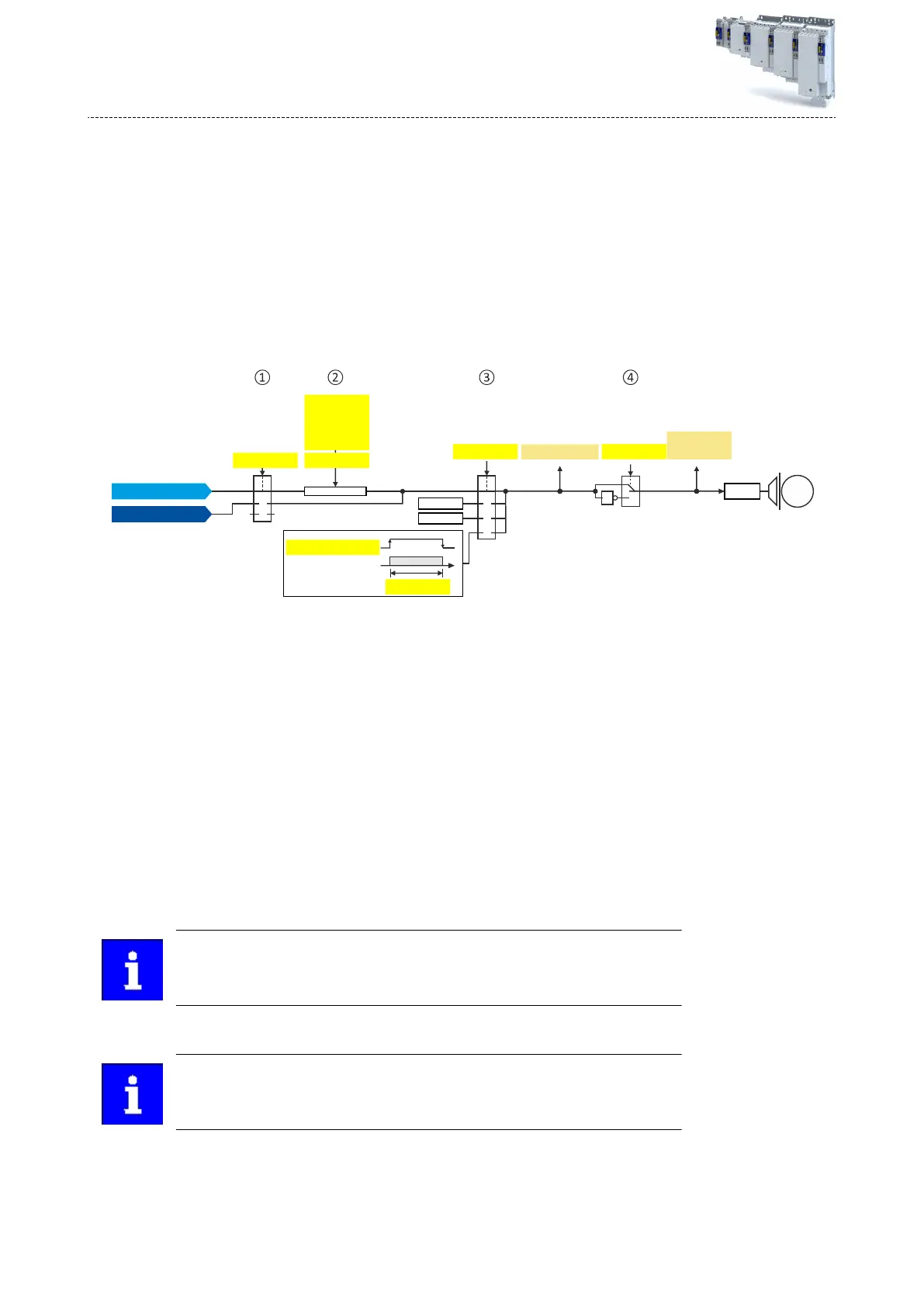
Explains position error monitoring for servo control, comparing system deviation to tolerance and defining error response.
Details the default mapping for the velocity mode, including parameters received from and sent to the controller.
Describes the default mapping for the cyclic sync velocity mode, covering control words, status words, and operating modes.
Explains speed deviation monitoring for servo control, comparing system deviation to tolerance and defining error response.
Describes the default mapping for the cyclic sync torque mode, including control words, status words, and parameters for speed and torque limits.
Explains how to access parameter settings for motor feedback systems via EASY Starter, offering choices for resolver or encoder.
Explains pole position identification for synchronous motors, including requirements, methods, and monitoring.
Describes the servo control for synchronous motors, detailing preconditions and required commissioning steps.
Details the servo control for asynchronous motors, covering preconditions and required commissioning steps.
Monitors thermal utilization of the motor using currents and a mathematical model, including speed-dependent evaluation and UL 508 compliance.
Monitors instantaneous motor current for protection, highlighting the importance of adapting the threshold and setting the maximum output current.
Covers preconditions, automatic and manual configuration of the engineering port, including IP address, subnet mask, and gateway.
Explains the inverter's i*t utilization calculation for thermal overload protection, including warnings and error thresholds.
Explains the STO safety function which prevents the motor from generating torque and movements, ensuring safe disconnection.
Details the SSE safety function, which has the highest priority and triggers based on external stop requests.
Explains ramp monitoring for stop functions SS1 and SS2, ensuring deceleration ramps are not exceeded and triggering error stops.
Describes the SS1 safety function that monitors stopping time and switches the inverter to STO if the time elapses or speed is too low.
Explains the SS2 safety function that monitors drive speed within tolerance windows and switches to SOS or STO.
Details the SOS function where the drive is not switched to torque-free operation, maintaining reached position and active control functions.
Monitors compliance with the safe maximum motor speed, triggering an error message if exceeded.
Monitors the parameterized speed limit (Nlim) and triggers an error stop if limits are exceeded or braking time elapses.
Allows setting a maximum permissible position change and initiates an error stop if limits are exceeded.
Monitors motor rotation direction and parameterizable tolerance ensures drive does not change permissible direction.
Monitors drive speed as a function of absolute position, allowing use of physically limited motion range without mechanical buffers.
Switches between normal and special operation, activating safety functions like STO, SS1, SS2, SLS, and SLI.
Allows overriding normal stop functions (STO, SS1, SS2) during special operation and repair mode.
Moves the drive from a blocking situation ('Deadlock'), restricting safety functions to STO, SS1 and monitoring effectiveness of enable switch.
Allows synchronized shutdown of an entire drive network, typically triggered by STO stop function.


