19.25 Diagnoscs
19.25.1 LED status display
On its front, the inverter indicates the "STO acve" device state via the right "RDY" LED.
You can gather the meaning of the "RDY" and "ERR" LEDs (le side) from the following two
t
ables:
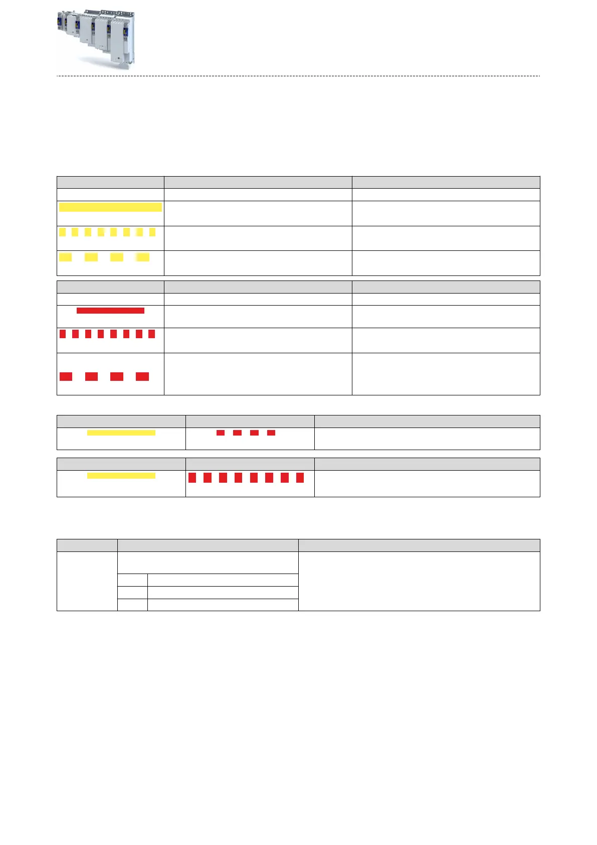
LED "RDY" (yellow) State Meaning
o - No status message acve
On (yellow)
- Restart acknowledgement requested
Blinking yellow 2 Hz
SOS acve
Blinking yellow 1 Hz
Service state Parameter set transfer requested.
"ERR" LED (red) State Meaning
o - The device is working correctly.
on (red)
Crical device error The device is defecve and must be replaced.
Blinking red 2 Hz
Bus error Safety
communicaon interrupted.
Blinking red 1 Hz
Error detecon in the safety system One of the following errors has been detected:
•
Speed e
xceeded
•
Discrepancy of the inputs
•
Acknowledgable errors
19.25.1.1 LED status during parameter set transfer
LED "RDY" (yellow) "ERR" LED (red) Meaning
On Blinking 1Hz
At start-up, a
modied parameter set has been detected. Acknowl-
edge with buon S82.
LED "RDY" (yellow) "ERR" LED (red) Meaning
on
Blinking 2 Hz
A modied safety address has been detected during the parameter
se
t transfer in the "Init" state. Acknowledge with buon S82.
19.25.2 Error history
buer
Parameter
Address Name / seng range / [default seng] Info
0x2130:001 Fault history: Actual fault type
•
R
ead only
0 No response
1 Fault > CiA402
2 Warning
Safety funcons
Diagnoscs
LED status display
429
 Loading...


