6.4 System bus communicaon
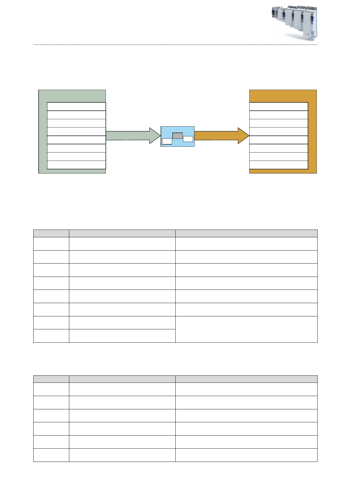
The system bus serves to transfer cyclic-synchronous master values. For the transfer, 8 input
w
ords and 8 output words are available, with a data width of 32 bits each. The assignment of
the double words is shown in the gure "Assignment of system bus input/output".
FB
FB
TM
Control module
System bus out parameter
Cycle length (0x5021:150)
Position (0x5021:151)
Velocity (0x5021:152)
Acceleration (0x5021:153)
Torque (0x5021:154
Time stamp TP (0x5021:155)
TA specific (0x5021:XXX)
TA specific (0x5021:XXX)
Cycle length (0x5021:160)
Position (0x5021:161)
Velocity (0x5021:162)
Acceleration (0x5021:163)
Torque (0x5021:164
Time stamp TP (0x5021:165)
TA specific (0x5021:XXX)
TA specific (0x5021:XXX)
System bus in parameter
System bus inputs System bus outputs
Fig. 25: Assignment of system bus inputs/outputs
Informaon on network
conguraon4EtherCAT system bus ^ 342
6.4.1 Inputs
The following parameters are available for the diagnoscs of the system bus input values:
Parameter
Address Name / seng range / [default seng] Info
0x5021:150 System bus diagnoscs: Cycle length (input value)
•
R
ead only
Cycle length of the master axis
0x5021:151 System bus diagnoscs: Posion (input value)
•
Read only
Master posion value
0x5021:152 System bus diagnoscs: Velocity (input value)
•
Read only
Speed conducvity
0x5021:153 System bus diagnoscs: Acceleraon (input value)
•
Read only
Acceleraon conducvity
0x5021:154 System bus diagnoscs: Torque (input value)
•
Read only: x.xx Nm
Torque of the master axis
0x5021:155 System bus diagnoscs: Time stamp (input value)
•
Read only: x ns
Time stamp of the master axis
0x5021:156 System bus diagnoscs: Input data word 6
•
Read only
This system bus input word is currently not used, but can be connected
in the technology applicaon by the user.
0x5021:157 System bus diagnoscs: Input data word 7
•
Read only
6.4.2 Outputs
The following parameters are available for the diagnoscs of the system bus output values:
Parameter
Address Name / seng range / [default seng] Info
0x5021:160 System bus diagnoscs: Cycle length (output value)
•
R
ead only
Cycle length of the source set via Master value output of system bus
0x5020:001.
0x5021:161 System bus diagnoscs: Posion (output value)
•
Read only
Master posion value of the source set via Master value output of sys-
tem bus 0x5020:001.
0x5021:162 System bus diagnoscs: Velocity (output value)
•
Read only
Master speed value of the source set via Master value output of system
bus 0x5020:001.
0x5021:163 System bus diagnoscs: Acceleraon (output value)
•
Read only
Master acceleraon value of the source set via Master value output of
system bus 0x5020:001.
0x5021:164 System bus diagnoscs: Torque (output value)
•
Read only: x.xx Nm
Torque of the master axis of the source set via Master value output of
system bus 0x5020:001.
0x5021:165 System bus diagnoscs: Time stamp (output value)
•
Read only: x ns
Time stamp of the touchprobe source in ns selected via source TP1
0x5020:011.
Technology applicaon (TA) basic sengs
System bus
communicaon
Inputs
84
 Loading...


