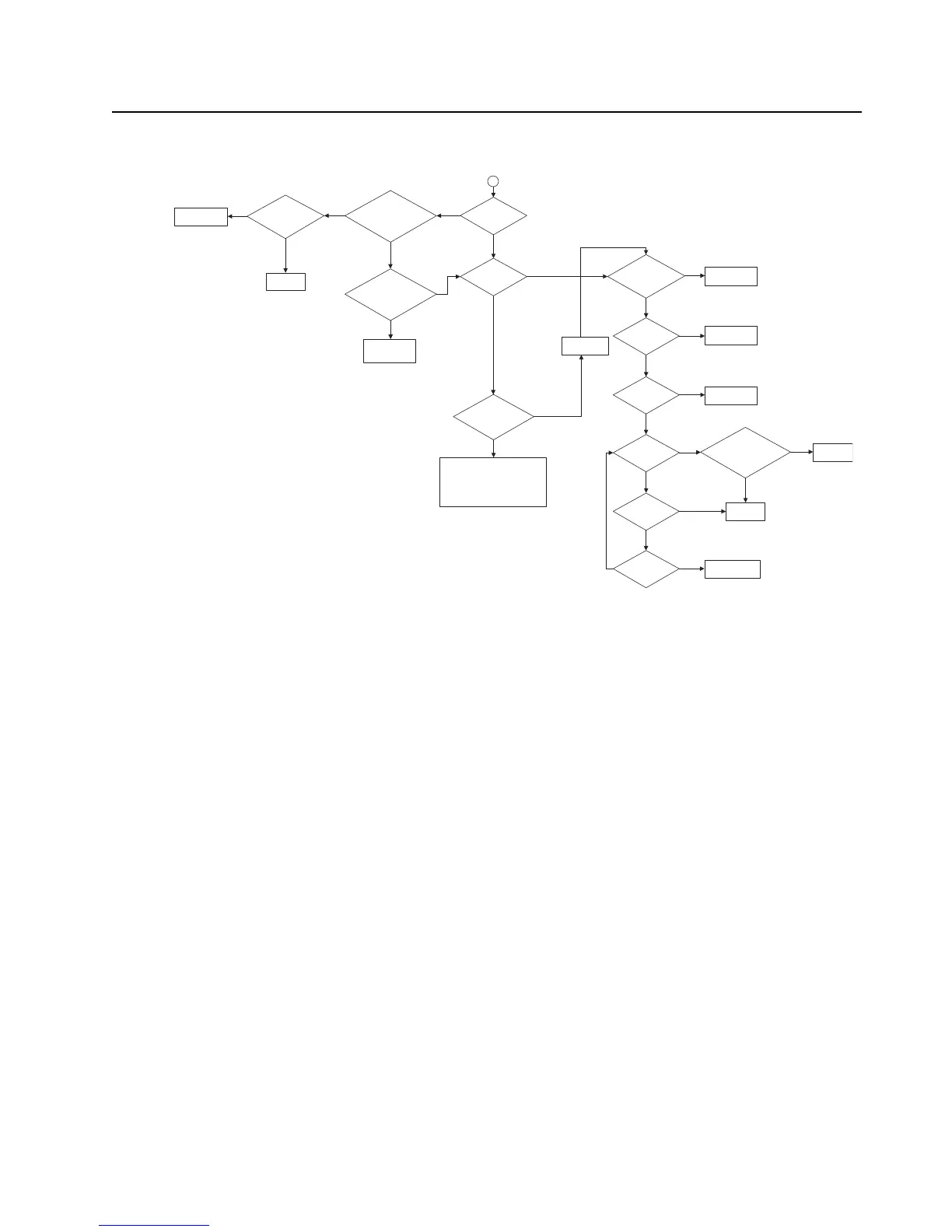
Troubleshooting Charts: VCO Failure 5-39
VCO Failure – Page 2 (UHF1)
Is power at
C3161
>-20dBm?
Take continuity
check of traces to
U702.
1
At Rx, is L701 high and
L702 low?
At Tx, is L701 low and
L702 high?
Is power at U3001 input
Tx: C3112
Rx: C3102
>-20dBm?
Check continuity at
L701 and L702.
Fault found?
Check parts around
U3001. If OK ,
replace U3001.
Replace suspected
compone nts.
Replace U702.
Control voltage
at R705
0.3< V dc< 10.6?
Is Vdc = 4.55V at pin
3 of Q3123 during
Rx and at Q3156
during Tx?
Is V dc at C742 5V,
Vdc at C726, C734,
C737 2.775V?
Is Vdc at Y701
pin 4 2.775V?
16.8MHz at pin
3 of Y701 and
C736?
16.8MHz at
L753?
10.8Vdc at pin2
of D723?
2.775Vdc at pin
4 of D722?
Check and visual
inspect U746 circuitry.
Fault found?
Check 2.775V and
5V supply.
Check 2.775V
supply.
Replace Y701
and/or C736.
Replace the
suspected
compone nts.
Replace U702.
Check D722, D723,
C716, C717, C718,
C719.
No
Yes
Yes
Yes
Yes
No
Yes
No
No
Yes
No
No
Yes
Yes
Yes
Yes
No
No
No
No
No
No
Yes
Yes
No
Yes
For Tx: Check and visual inspe ct D3135 -
D3138, C3140, C3141, C3143, C3147,
L3139, L3145.
For Rx: Check and visual inspect D3102 -
D3105, C3107, C3108, C3110, C3113,
L3106, L3112.

 Loading...