3-14 Theory of Operation: Main Board
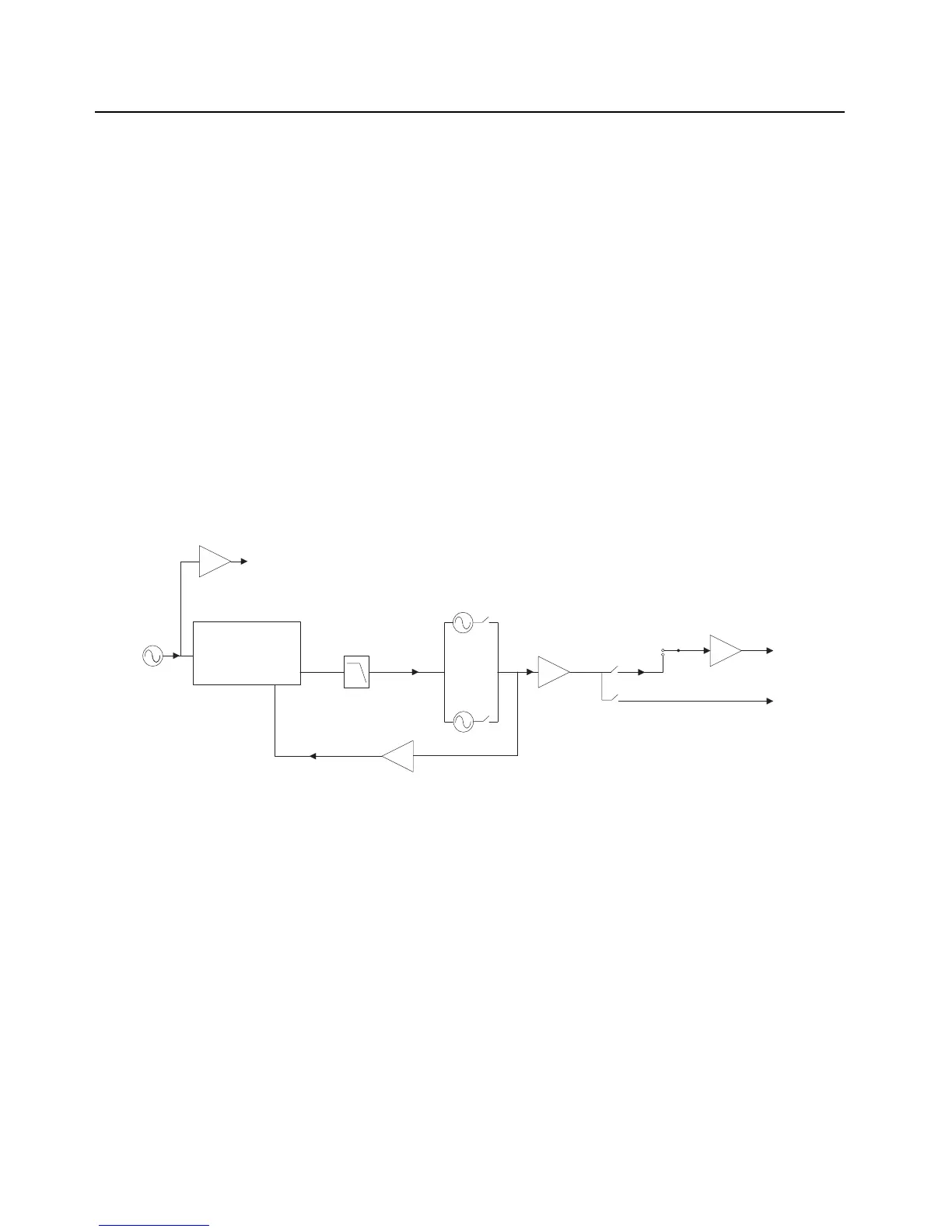
3.1.4 Frequency Generation Unit (FGU)
The frequency-generation function is performed by several ICs; multiple voltage-controlled
oscillators (VCOs); and associated circuitry. The reference oscillator provides a frequency standard
to the Trident IC, which controls the VCOs. There are also buffers that amplify the VCO signal to the
correct level for the next stage. Figure 3-12 and Figure 3-14 below shows a block diagram of the
FGU Section.
UHF1/ UHF2: Two VCOs are employed: one to generate the first RX LO and the other to generate
the transmit injection signals.
VHF: Two VCOs are employed: one to generate the first RX LO and the other to generate the
transmit injection signals.
700–800 MHz: Three VCOs are used to cover the entire 700/800 MHz band.
• VCO1 covers the RX 800 MHz band and the TX 700 MHz (764–776 MHz) band
• VCO2 covers the TX 700/800 MHz (794–824 MHz) band
• VCO3 covers the TX 800 MHz (851–870 MHz) band and the RX 700 MHz band
NOTE: Refer to List of Transceiver Schematics and Board Overlays for a listing of FGU-related
schematics that will aid in the following discussion.
Figure 3-12. Synthesizer Block Diagram (UHF1/ UHF2)
TRIDENT IC
LOOP
FILTER
PRESCALAR
BUFFER
16.8MHz
16.8MHz
BUFFER
PRE
BUFFER
TX LO
RX LO
TX
BUFFER
UHF1/ UHF2 RX
TX VCO
RX VCO
16.8MHz REFERENCE CLOCK (To Controller and Abacus IC)
UHF1/ UHF2 TX

 Loading...