Troubleshooting Tables: List of Board and IC Signals 7-5
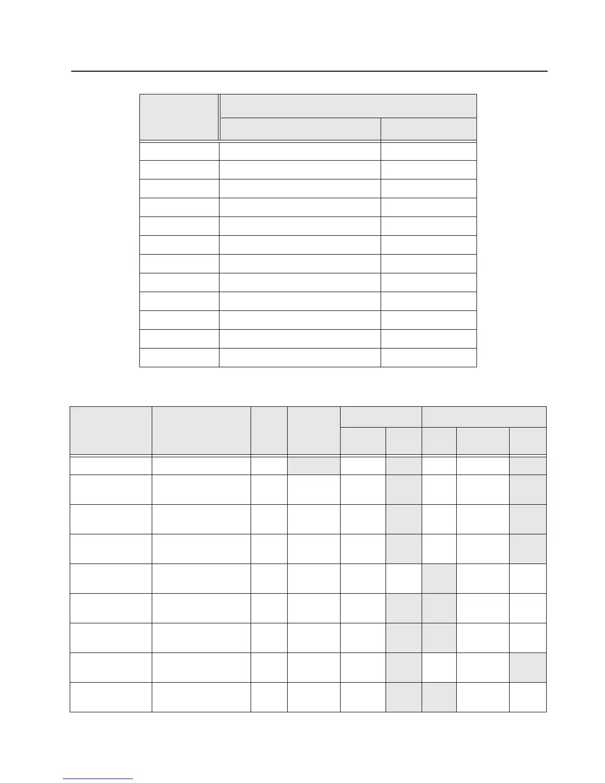
Table 7-6. NFC Flex connector interface Pin-Out
Test Place
Main Board
Signal Name Pin #
GND P1-1
GND P1-2
TX_RX_LED_AMBER P1-3
V_Sw_5 P1-4
TX_RX_LED_RED P1-5
V_Sw_5 P1-6
TX_RX_LED P1-7
GND P1-8
BT_BLUE P1-9
GND P1-10
GREEN_LED P1-11
Red_LED P1-12
Table 7-7. Overall GPIO pin functions
Signal Name Description
Pin or
Ball #
Active State
SW Initialized HW Reset
Direction
*
PU State Direction
*
PU
or
PD
NC NC M8 Output 0 Output
codec_cs DSP SPI chip select
for TI dual CODEC
Y1 0 Output 1 Output
abacus_cs DSP SPI chipselect
for Abacus IC
L3 0 Output 0 Output
trident_cs DSP SPI chipselect
for Trident IC
V6 0 Output 0 Output
synthesizer_lock RF synthesizer lock
detect
V15 1=Lock Input None Input None
f2_timer_dmcs Timer output compare
for DMCS or SYNCB
M20 1 Output
Input Pull-
down
mako_tx_rx Trigger for Mako DAC
ramp
L14 1=TX Output
*Input None
T_Display_Toggle Radio display
detection
G19 0 Output
0 Output
dac_cs RF DAC chip select T19 0 Output Input Pull-
down

 Loading...