3-56 Theory of Operation: Bluetooth
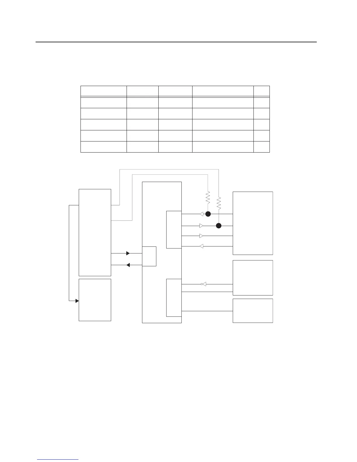
The host processor is connected to the 3.3V SDRAM using a synchronous interface. The host
processor is connected to the OMAP on the Main Board by a full-speed USB (D11 & D12). VBus is a
sense line only.
Figure 3-46. Bluetooth USB Interface To Main Board
Table 3-14. USB I/O
Signal Name Pin Name Pad Name Schematic Name I/O
GPIO19 C12 PA19 USB_BOOT_3.3V I
GPIO20 D10 PA20 ATMEL_BOOT I
DP D11 – BT_AVR_USB_DP I/O
DM D12 – BT_AVR_USB_DM I/O
VBUS E12 – BT_AVR_VBUS I
TI NL 5500
Bluetooth/GPS
ATMEL AVR32
AT32UC3A0512
Low Frequency
Receiver AS3930
DAT
CL_DAT
LF Transmit
(OR Gate)
HCI_TX
USART0
USART1
USART2
Debug RX
Debug TX
BT Debug
Flex
J2401 Connector
PB29
K6
Pin 33
Pin 34
Pin 25
Pin 26
K7
PB30
PA00
PA01
PA03
PA04
PA05
PA07
PA06
A4
B5
B4
B7
9
10
J6
H6
J7
J8
K11
J10
L12
HCI_RX
HCI_CTS
HCI_RTS

 Loading...