Theory of Operation: Controller 3-21
3.2 Controller
3.2.1 Controller Overview
This section provides a detailed circuit description of the APX 3000 controller design. The controller
design consists of the following board and flexes:
Printed Circuit Boards
• Main Board
Flexes
• Main Flex
• Side Controls
•Top Control
• NFC with LED
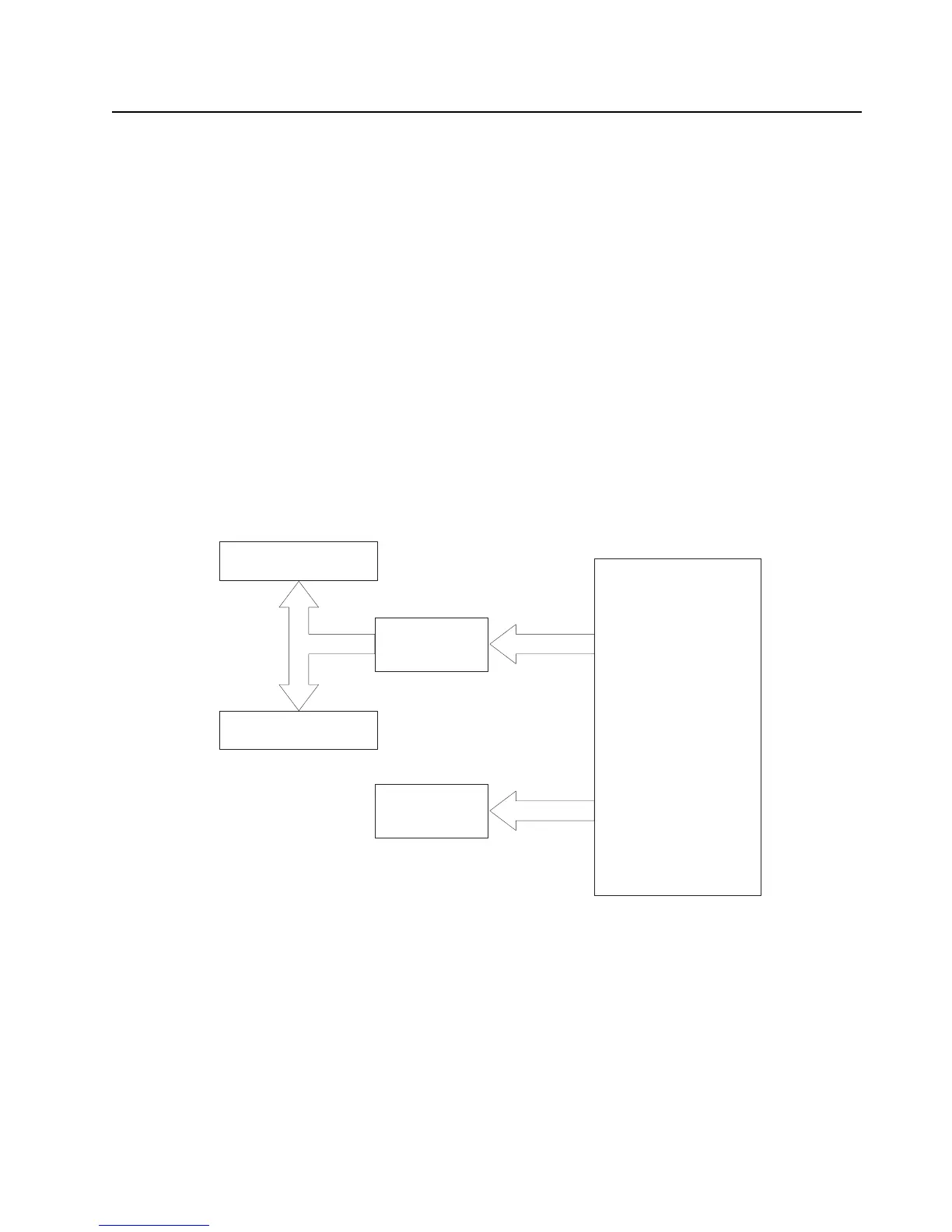
The controller interconnection diagram (Figure 3-12) shows the various physical components of the
design, along with how they are all connected. It also shows the key distinguishes between a flex
connection and a board-to-board connection. A brief description of each of the components is
provided below.
Figure 3-15. Controller Interconnection Diagram
3.2.1.1 Main Controller Components and Connections
3.2.1.1.1 Main Board Controller section
The controller section contains the OMAP1710 dual-core processor, FLASH and SDRAM memory,
Audio circuitry (MAKO and CODEC IC's), a Complex Programmable Logic Device (CPLD), AVR
controller IC for Bluetooth 2.1 and support circuitry, a 3-axes digital accelerometer, a Type III
encryption IC and interfaces to the other components in the controller design.
Main Flex
Side Control
Top Control
Main board
NFC with
LED

 Loading...