Chapter 5 Troubleshooting Charts
This section contains detailed troubleshooting flowcharts. These charts should be used as a guide in
determining the problem areas. They are not a substitute for knowledge of circuit operation and
astute troubleshooting techniques. It is advisable to refer to the related detailed circuit descriptions in
the theory of operation sections prior to troubleshooting a radio.
5.1 List of Troubleshooting Charts
Most troubleshooting charts (see Table 5-1) end up by pointing to an IC to replace. It is not always
noted, but it is good practice to verify supplies and grounds to the affected IC and to trace continuity
to the malfunctioning signal and related circuitry before replacing any IC. For instance, if a clock
signal is not available at a destination, continuity from the source IC should be checked before
replacing the source IC.
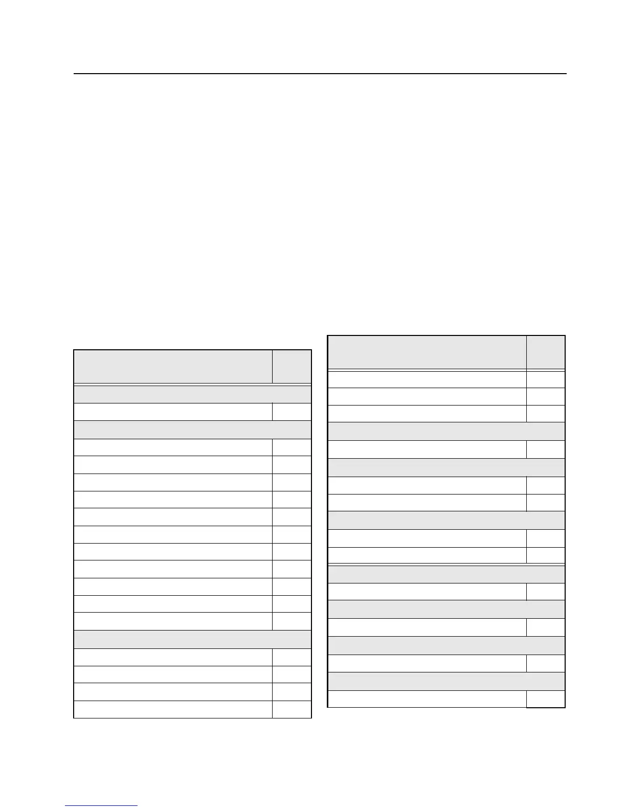
Table 5-1. Troubleshooting Charts
Troubleshooting
Page
No.
Main Troubleshooting
Main Troubleshooting Flowchart 5-3
Power-Up Failure
Main Board 5-4
B+ Incorrect Voltage 5-5
Low LDO10 V_3.3 Voltage 5-6
Low LDO3 V_1.55 Voltage 5-7
Low LDO8 V_5.0A Voltage 5-8
Low VBUS2 Voltage 5-9
Low V_SW_1.4 Voltage 5-10
Low V_2.23 Voltage 5-11
Low V_SW_3.6 Voltage 5-12
Low V_SW_5 Voltage 5-13
Low V_EXT_1.85 Voltage 5-14
DC Supply
DC Supply 5 Volt Failure 5-15
DC Supply 3.6 Volt Failure 5-16
DC Supply 3 Volt Failure 5-17
DC Supply 1.85 Volt Failure 5-18
DC Supply 1.8 Volt Failure 5-19
DC Supply 1.5 Volt Failure 5-20
DC Supply 1.4 Volt Failure 5-21
Button
Side Button Error 5-22
Audio
External Audio 5-23
External Mic Failure 5-24
Keyload/ Secure Hardware/ Memory
Keyload Failure 5-25
Secure Hardware Failure 5-26
RX RF
RX RF Failure 5-27
FGU
FGU Failure 5-37
VCO
VCO Failure 5-38
GPS
GPS Failure 5-43
Table 5-1. Troubleshooting Charts (Continued)
Troubleshooting
Page
No.

 Loading...