Theory of Operation: Controller 3-39
3.2.6.2 Side Controls
The side controls include four programmable, buttons (Side Top Button,Side Middle Button, Up
arrow and Down arrow). These components interface to the main flex via a connector through side
control flex. The main flex routes the side controls signals to main board through connector J1. See
Chapter 7 for pin out names and numbers.
Up Arrow Button (R4006), Down Arrow Button (R4007) and the top side button (R6101) are inputs to
the CPLD and are biased to 1.875V. A button press is detected when the OMAP reads a 'LO' state
from the CPLD EMIFS interface. Middle side button (R4005) is connected directly to OMAP and a
button press is detected when a LO state is read.
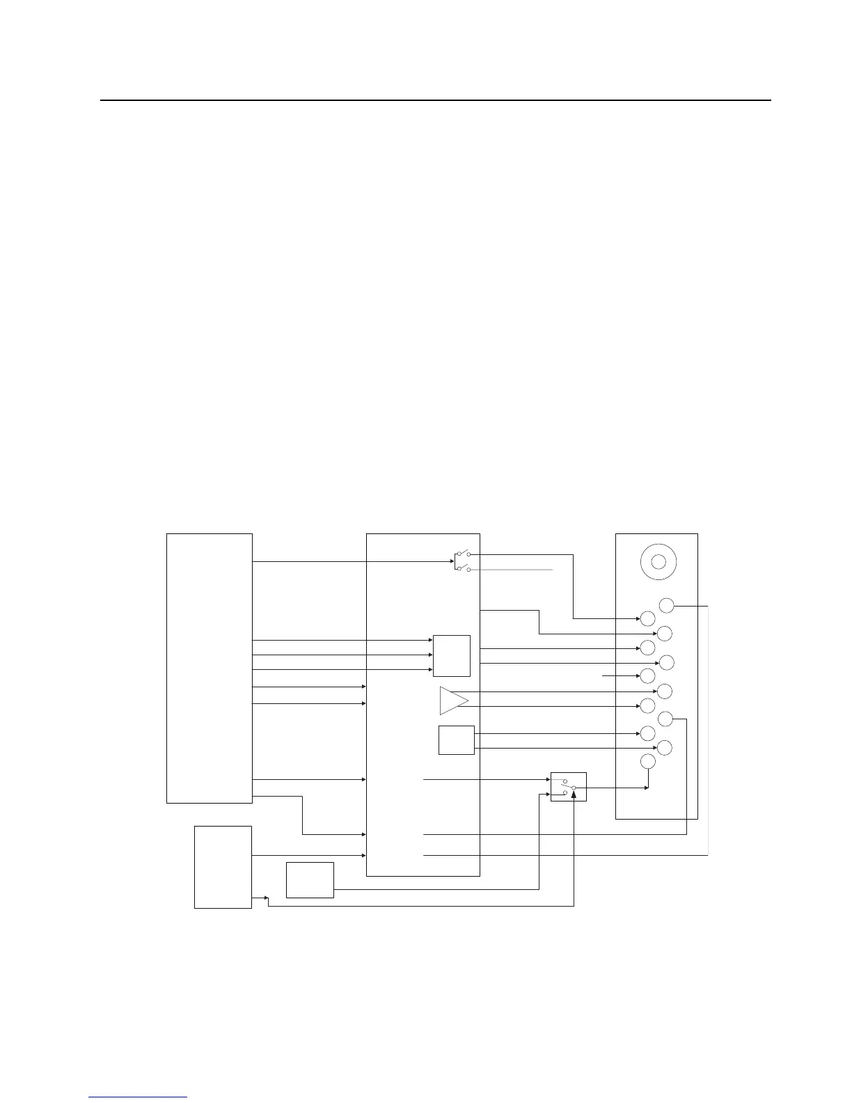
3.2.6.3 GCAI
The GCAI (Global Communications Accessory Interface) connector is a 15 pin interface located on
the side of the radio. The connector interfaces the radio with accessories and is used for
programming. When the OMAP (U6501) detects that an accessory has been attached through a
logic low on GPIO0, it will identify the device by reading the GCAI_ONE_WIRE line. Once the device
type is identified, the appropriate signals are multiplexed through MAKO to the main flex connector
for the particular device. Figure 3-31 is a block diagram of the GCAI interface.
Mounted to the side connector is a flex that houses ESD protection circuitry. The universal side
connector interfaces with the main flex via the J2 connector of the main board. The figures below
show the connections and signal assignments from the universal connector to the controller board.
Figure 3-31. GCAI Signal Configuration
2
6
7
8
9
10
11
12
D+
D-
Vbus
One-Wire
ONE_WIRE
GPIO_4
GPIO_3
Preamp
USB
XCVR
1
3
4
5
One-Wire
GPIO_0
Ext Mic
GCAI
CONNECTOR
UART1_TX
UART1_RX
UART1_TX
UART1_RX
OPT_GPIO_3
OPT_GPIO_2
OPT_GPIO_0GPIO
MAKO
OMAP1710
EXT
PA
KF Switch
CPLD
GPO
ONE_WIRE_GCAI
BATT_STATUS
VBUS
D+
D-
SPKR+
SPKR-
GND
MIC+
MIC-
OPTA_SEL_2
OPTA_SEL_1
OPTA_SEL_0
KEYFAIL CONTROL
KEYFAIL
MACE
TXEN
DAT
SE0
USB
PORT 0
GPIO
GPIO

 Loading...