Theory of Operation: Main Board 3-15
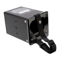
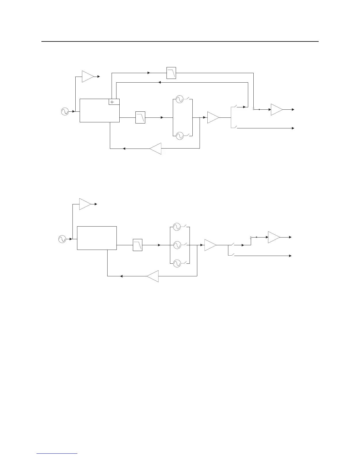
Figure 3-13. Synthesizer Block Diagram (VHF)
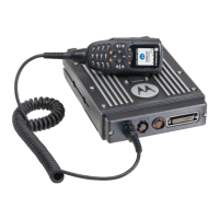
Figure 3-14. Synthesizer Block Diagram (700/800 MHz)
3.1.4.1 Reference Oscillator Y701
The radio's frequency stability and accuracy is derived from the Voltage-Controlled Temperature-
Compensated Crystal Oscillator (VCTCXO), Y701. This 16.8 MHz oscillator is controlled by the
voltage from the AUX_DAC pin of the Trident IC, U702, that can be programmed through a serial
peripheral interface (SPI). The oscillator output at pin 3 is coupled through capacitor C736 to the
Trident IC reference oscillator input. This reference is then passed through an internal buffer and is
then coupled to the external BJT buffer (comprised of U746 and supporting circuitry) via C739.
These buffers provide isolation for the 16.8 MHz output to the controller circuitry and ABACUS IC.
Components L753 and C754 form a low-pass filter to reduce the harmonics of the 16.8 MHz.
TRIDENT IC
LOOP
FILTER
PRESCALAR
BUFFER
16.8MHz
16.8MHz
BUFFER
PRE
BUFFER
2
TX LO
RX LO
TX
BUFFER
VHF DIVIDE-BY-2
2
ND
HARMONIC FILTER
VHF TX
VHF RX
TRIDENT IC
LOOP
FILTER
PRESCALAR
BUFFER
16.8MHz
16.8MHz
BUFFER
PRE
BUFFER
TX LO
RX LO
TX
BUFFER
7/800 RX
VCO 1
VCO 2
VCO 3
16.8MHz REFERENCE CLOCK (To Controller and Abacus IC)
7/800 TX

 Loading...