3-34 Theory of Operation: Controller
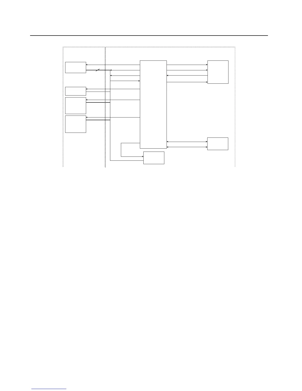
Figure 3-26. SPI and I2C Configuration
3.2.4.8.5 1-Wire
The OMAP's 1-wire line is available on the Main Board Connector J1 pin 9. The signal is routed
through Main flex.
3.2.4.8.6 USB
The OMAP CPU's USB port is routed to the side connector via J1. The USB signals on the side
connector are illustrated in Figure 3-22.
3.2.4.8.7 UARTs
Two of OMAP's UARTs are configured for peripheral interfacing.
The four-wire UART1, which is capable of hardware flow control, is available on the side connector
for accessory devices. The signals are level translated via MAKO and routed to the side connector
via J1.
OMAP's UART2, which is a two wire interface, capable of software flow control only, is connected to
the GPS receiver IC on the Main board.
OMAP 1710
McBSP3 SPIF
DSP SPI
MAKO
TI CODEC
ARM SPI
I2C
LIGHTING
CONTROLLERS
3
SPI_CLK
SPI_MOSI
SPI_MISO
MAKO_CS
I2C_SCL
I2C_SDA
SPI_DSP_CLK
SPI_DSP_MOSI
SPI_DSP_MISO
DAC_CS
EEPROM_CS
ABACUS_CS
ABACUS_CS
DSP SPI
TRIDENT
ABACUS
EEPROM
DAC
RF SECTION
CONTROLLER SECTION
CODEC_CS
I2C

 Loading...