December 6, 2004 68P81083C20-D
7-26 Controller Section Theory of Operation: Audio and Signalling Circuits
Hear Clear IC (Refer to schematic page 10-26 for reference)
The Hear Clear (HC) is typically used for 900 MHz radios. The HC has 3 main circuit blocks within
the IC which are used by this radio; 1) Compressor, 2) Flutter Fighter, and 3) Expander circuits.
There are 6 enable lines on the Hear Clear IC which determine its mode of operation. The IC ENAB
line U0250-C4 is tied to SW B+, so whenever the IC is placed it is always active. The remaining 5
lines are controlled by the ASFIC General Control Bit lines, GCB0, GCB1, GCB3, GCB4, and GCB5.
The table below summarizes their logic states.
TX1: transmit mode with carrier squelch, PL or DPL.
RX1: receive voice with carrier squelch, PL or DPL.
TX2: transmit mode with all other data HST/MDC/MPT/DTMF etc.
RX2: refers to receive mode with all other data HST/MDC/MPT/DTMF
Logic State “X” means either 1 or a 0, i.e. “don’t care”.
Transmit Path for Radios with Hear Clear
For transmit, the signal comes from the appropriate microphone and enters the ASFIC at U0200-A7
or U0200-B6 as would standard TX audio. After entering the ASFIC, the signal is internally routed to
U0200-A6 ASFIC MIC AMP OUT, where it leaves the ASFIC and enters the Hear Clear compressor
at U0250-D3. The signal then exits the compressor at U0250-F3, where it is routed back to the
ASFIC (U0200-C7). C0261 provides AC coupling. Inside the ASFIC the signal goes through an LPF
and HPF which band limit the signal between 300 - 3 kHz. The signal is then pre-emphasized and
exits the ASFIC at U0250-C8, passes through a coupling cap and enters the ASFIC at U0200-E8.
Again inside the ASFIC the signal goes through a limiter, splatter filter, and a pair of attenuators
which set the amplitude (deviation level) of the signal.
The Compressor is used in transmit mode. The purpose of this circuit is twofold; 1) improve S/N ratio
for low level audio, and 2) maintain the same dynamic range of a 12.5 kHz bandwidth channel as is
obtained in a 25 kHz bandwidth channel.
The compressor raises low level signals and lowers high level signals. The compressor circuit
produces a signal whose output voltage (U0250-F3) is based on the input voltage level (U0200-A6)
of the signal. It is NOT a function of frequency (as is Preemphasis). The voltage transfer function is:
COMPOUT == SQRT[ 80*ASFICMICAUDOUT ]
Notice that 80 mV in yields 80 mV out. Some example levels are:
• 20 mV input == 40 mV output
• 80 mV input == 80 mV output
• 150 mV input == 110 mV output
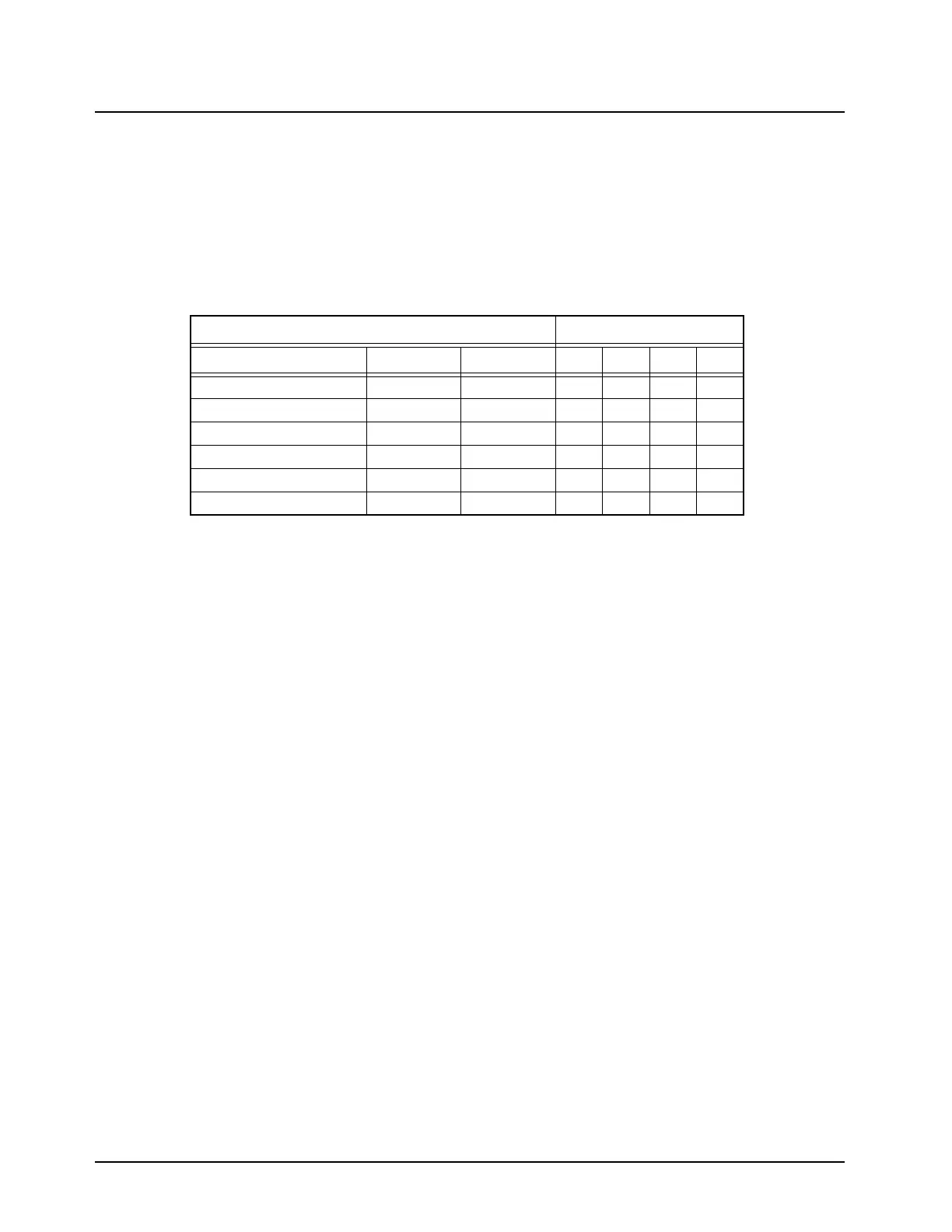
Table 7-3. Hear Clear Enable Lines Configuration
Logic State
Name Ref. Des Set By TX1 RX1 TX2 RX2
Ic Enable U0250-C4 SW B+
11X1
Flutter Fighter Enable U0200-B5 U0200-B5
X1X0
LO Clamp Disable U0250-A5 U0200-B3
111X
Hi Clamp Enable U0250-C2 U0200-C4
00X0
HCI Disable U0250-B6 U0200-A3
11X1
Compander Enable U0250-D1 U0200-A2
11X0
 Loading...