December 6, 2004 68P81083C20-D
5-2 Disassembly & Reassembly and Replacement Procedures: Disassembly to Transceiver Board Level
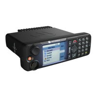
4. Pull the control head off of the transceiver until pressing the snaps. (Go to “Remove the Top
Cover” section below).
Remove Front Housing
Remote Mount Version Models Only
1. Disconnect the Remote Mount Cable by squeezing the top and bottom of the connector
together, disengaging the bottom snap then the top and pulling straight out.
2. Insert a small flat-blade screwdriver or like instrument in the side groove at the interface
between the remote front housing and the transceiver (see Figure 5-1). Press while pulling
the housing away from the transceiver until the snap releases. Repeat the operation on the
opposite side.
3. Pull housing off the transceiver.
4. Remove white retainer (p/n 4205395X01) from the header (or front housing).
5. Remove the 18 position connector from the front of the transceiver.
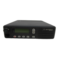
Remove the Top Cover
Low Power Models
1. Pry the cover free from the chassis by inserting a small flat-blade screwdriver or like instru-
ment into the area shown in Figure 5-2 and rotating the handle of the screwdriver over the top
of the radio. This will disengage the snap between the cover and chassis. Rotate the cover
away from the chassis and pull off. (Go to “Remove the Cavity Shield” paragraph, page 3).
Figure 5-2. Removing the Top Cover - Low Power Models
The control head must be removed before removing the
transceiver top cover.
!
a u t i o
Disengage Snap He
 Loading...