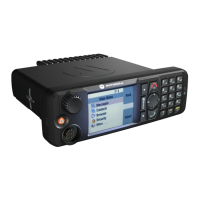
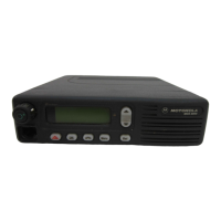
68P81083C20-D December 6, 2004
Disassembly & Reassembly and Replacement Procedures: Transceiver Reassembly High Power Models 5-17
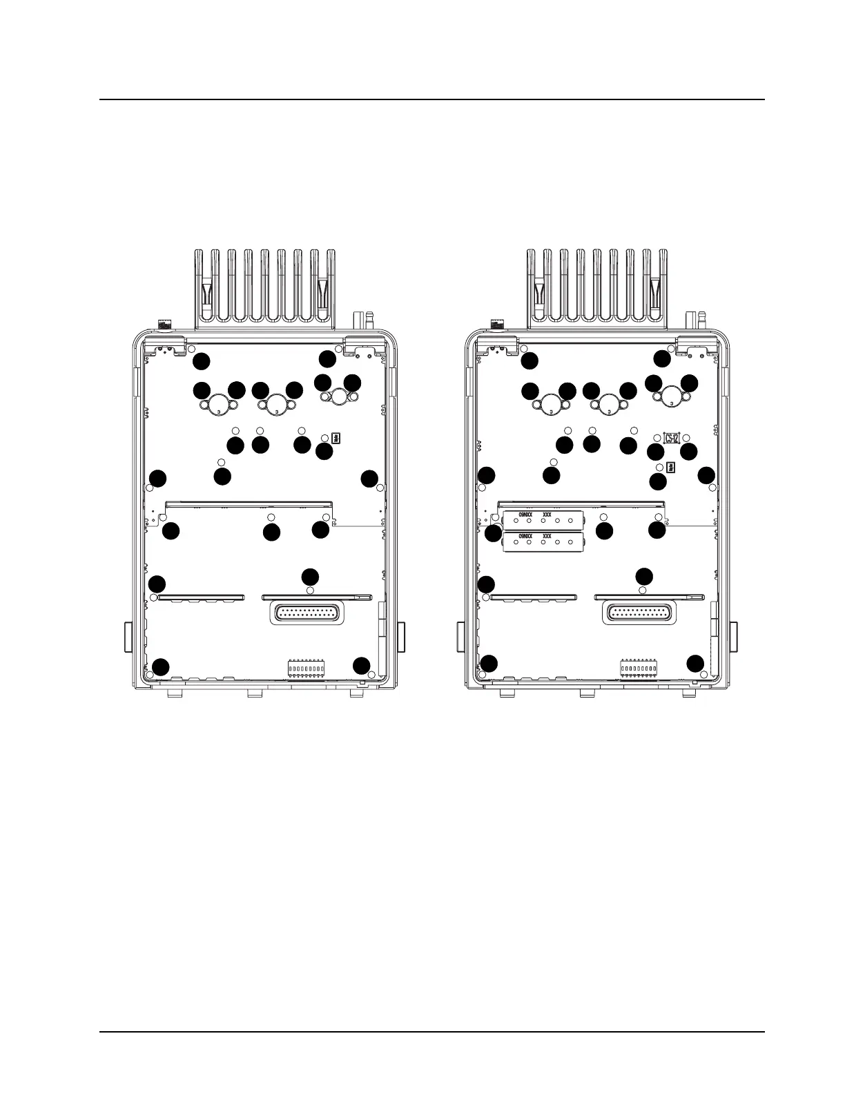
NOTE: Observe the screw-down sequence in Figure 5-21 when installing screws. Proper alignment
of boards depend on following this sequence.
7. Fasten screws #1-6 to 12 in lbs of torque using a T-8 Torx driver. Fasten the remaining
screws (#7-20 for VHF models, #7-22 for UHF models) to 6-8 in lbs of torque using a T-10
Torx driver following the screw down sequence in Figure 5-21.
Figure 5-21. Reassembly Screw Down Sequence
8. Install the Audio PA clip to the corner of the chassis (per Figure 5-22) by applying downward,
equal pressure to the side and main tab of the clip. Side pressure on the clip will negatively
impact heat sinking of the 5 V Regulator and Audio PA. The placement tab should rest flush
against the top of the chassis wall.
1
1
2
2
3
3
4
1
4
2
5
6
6
7
7
8
8
9
9
10
10
11
11
12
12
13
13
14
14
15
15
16
16
17
17
18
18
19
20
20
21
21
22
22
VHF
UHF
1
1
2
2
3
3
4
1
4
2
5
6
6
16
16
15
15
7
7
8
8
12
12
11
11
10
10
14
14
17
17
9
9
19
13
13
22
22
18
18
20
20
21
21
20
23
20
24
 Loading...